This thread has been locked.

If you have a related question, please click the "Ask a related question" button in the top right corner. The newly created question will be automatically linked to this question.

TDC7200: Schmitt Triggered Comparators on inputs?

Part Number: TDC7200
Other Parts Discussed in Thread: TDC1000

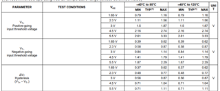
The TDC7200 datasheet includes a block diagram that indicates "Schmitt Triggered Comparators" on the START/STOP inputs. But the electrical specifications seem to contradict this.
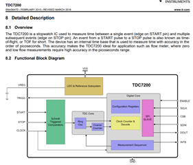


Which is correct?

Based on other answers in these forums I believe the block diagram is incorrect, and there are no hysteretic comparators.  But I would like confirmation.

  • Hello Jason,

    Thanks for posting to the sensors forum.

    You are correct that there seems to be no hysteretic components mentioned but Schmitt Triggered comparators can also be used to convert slow rising edges into fast rising edges. Which would explain the comments in the previous post you referenced, a fast edge is needed in order to time your signal properly.

    Another thing to note is that the hysteresis can be tuned, so perhaps the Schmitt Triggers were tuned to have a very large hysteresis so they are not as sensitive to noise. Are the Schmitt Triggered comparators required for your application?

    Best,

    Isaac

  • This is a capture of our timing signals (two pairs):


    The probe setup here wasn't super clean, so the signals look worse than they actually are.  They have fast edges, but not enough voltage swing for the TDS7200 input high min of 0.7*VDD.  We intend to use 3.3V, so this is 2.3V, while our timing signals are approximately 1.2V. 

    We need digital level translation, but I think comparators with tight propagation delay tolerances would work great.  Do you have suggested parts?  Probably a dual with matched propagation delays through the comparator?

    Thanks!
    Jason


  • Hello Jason,

    Thanks for the info here. I am assuming the signals in your scope capture are the signals directly from your sensor. I think a comparator might work better in your application because you should be able to configure at which level to output your stop START or STOP signal. You might be able to get away with a level translator since you mentioned the signals are not as noisy as they are in this scope capture above but I personally prefer the comparator option since you will give the device a cleaner signal. I do not have any suggested parts to recommend here since I service the sensor side of our portfolio.

    My suggestion would be to make a new post regarding a comparator recommendation this will get an engineer familiar with the comparators we offer and if we have something that can meet your needs.

    I hope this helps!

    Best,

    Isaac

  • Thanks Isaac. 

    Will you be fixing this mistakes in the TDS7200 and TDS7201 datasheets?  Their diagrams both indicate that Schmitt trigger comparators are included on the inputs.  

  • Hey Jason, 

    Always glad to help out! I will be discussing with the design team on the specifics of the comparators. I am still not sure where that will lead but we first have to determine if the inputs are indeed Schmitt triggers or not.

    Once we settle on that answer then we can decide if any datasheet updates are needed.

    Best,

    Isaac 

  • Either way I think datasheet updates are needed. 

    If the inputs ARE NOT Schmitt trigger, then the diagrams need to be updated.  If they ARE Schmitt trigger, the input electrical specifications need to be updated to reflect their characteristics.

  • Thanks for the input Jason, it is definitely appreciated.

    Just as a quick question on my side, if they are Schmitt triggers what electrical specifications do you feel are missing and would help you understand the input section better?

    Best,

    Isaac

  • Hysteretic inputs are specified with thresholds and hysteresis, like this:


    The TDS7200 just specifies VIHmin and VILmax, with numbers consistent with a standard CMOS input:

  • Hey Jason,

    Technically you can already do this level of analysis, the input low and high levels are functions of V_DD. So if you know your VDD only has a range of 2V-3.6V then you can calculate the min high level and the max low level. The only difference that the TDC720x devices don't have are the max levels don't shift with the input voltage and we just defined as the max Vdd.

    So technically you can say:

    V_DD = 2V    MIN VIH- 1.4V

    V_DD= 2.5V  MIN VIH- 1.75V

    V_DD = 3V    MIN VIH- 2.1V

    V_DD= 3.3V  MIN VIH- 2.31V

    V_DD = 2V    MAX VIL- 0.6V

    V_DD= 2.5V  MAX VIL- 0.75V

    V_DD = 3V    MAX VIL- 0.9V

    V_DD= 3.3V  MAX VIL- 0.99V

    I do agree that the hysteresis could have a better definition, and my theory on this is that when the  TDC720x devices were designed they were designed with TDC1000 specifically in mind, so when it was originally specified the team was not focused on the other applications for this device. Your feedback is appreciated though I will definitely relay this over to the design team when we have our conversation.

    Best,

    Isaac