This thread has been locked.

If you have a related question, please click the "Ask a related question" button in the top right corner. The newly created question will be automatically linked to this question.

IWR1843: How to enable OSC_CLKOUT after sensorStart command

Part Number: IWR1843
Other Parts Discussed in Thread: AWR1243

Hi,

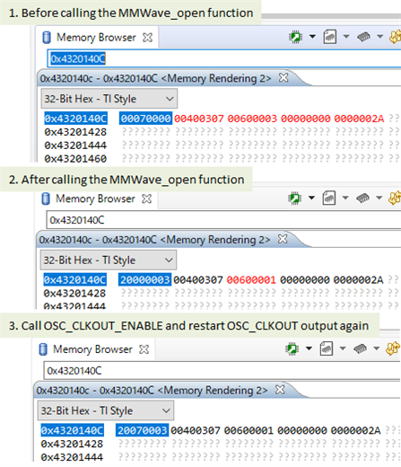
I want to output 40MHz clock to A14 OSC_CLKOUT pin on IWR1843 for debugging purposes based on SDK 3.5.0.4 demo.

By calling the following function in MmwDemo_initTask, it was confirmed that the 40MHz clock was output from the OSC_CLKOUT pin after the reset was released.

void osc_clkout_enable(void)
{
    uint32_t *regAddr = (uint32_t *)0x4320140C;
    uint32_t regValue;

    //https://e2e.ti.com/support/sensors-group/sensors/f/sensors-forum/929455/awr1843-how-to-turn-on-pin-function-osc_clkout?tisearch=e2e-sitesearch&keymatch=OSC_CLKOUT
    //For the analog output on pin A14 you can write the register "0x4320140C"  bit[26:16] with value '0x7' to enable the 40Mhz clockout on the OSC CLKOUT pin .
    SOC_MPUDisable();
    SOC_MPUDisableBackgroundRegion();
    SOC_MPUSetRegion(SOC_MPU_REGION12);
    SOC_MPUSetRegionBaseAddress(0x4320140C); /* required memory to read by the application */

    regValue = *regAddr;

    SOC_MPUSetRegionTypeAndPermission(SOC_MPU_NORMAL_OINC_NONSHARED, SOC_MPU_PRIV_RW_USER_RW_EXEC);
    SOC_MPUSetRegionSizeRegister(SOC_MPU_REGION_ENABLE | SOC_MPU_32_BYTES);

    SOC_MPUEnableBackgroundRegion();
    SOC_MPUEnable();

    *regAddr = regValue | 0x00070000;
}

However, when I execute the sensorStart command after configuration, the OSC_CLKOUT output stops.

I think that the register of the above code is overwritten by the sensorStart command, but I don't know where in the SDK it is overwritten.

Please tell me how to continue the OSC_CLKOUT output after the sensorStart command.

Best regards,

Hiroyuki Taguchi

  • Hi Hiroyuki,

    Thank you for your patience. I am forwarding this to the relevant team now.

    Best,

    Nate

  • In the meantime, could you put the device in debug mode, and pause execution when the pin is no longer oscillating? Then you could check the value of the register using CCS to see if it has changed.

    Best,

    Nate

  • Hi  Nathan,

    Thank you for your reply.

    I will check the register value. Please give me some time.

    Best,

    Hiroyuki

  • Hi  Nathan,

    The value of the register 0x4320140C is overwritten by the mmwave_open function call.

    Best,

    Hiroyuki

  • Hi Hiroyuki,

    Thank you for this information. We are still investigating this on our end. You could also try dragging in the mmwave folder found in C:\ti\mmwave_sdk_03_06_00_00-LTS\packages\ti\control into the CCS project and debug it again to step into the mmwave functions.

    Best,

    Nate

  • Hi Nate,

    Thanks,

    I'm still debugging here, but where is the register I'm stuck because I don't know if it's being overwritten.

    I feel that the RadarSS side receives a message from MSS and accesses the register.

    Best,
    Hiroyuki

  • Thanks for the information Hiroyuki. If the value of the register changed as you showed in the screenshots then I think it's being overwritten. Have you tried stepping through the mmwave_open() call as I recommended above?

    Best,

    Nate

  • Hi Nate,

    I may not have time for debugging during March.

    I will contact you if there is any progress.

    Thank you for your continued support.

    Best,

    Hiroyuki

  • Hi Hiroyuki,

    Can you try setting the value of this register after the channel config API is called? We believe that's where the value of this register is being altered. Additionally, can you tell us what firmware and patch versions you're using?

    Best,

    Nate

  • Hi Nate,

    I set a breakpoint at the beginning of the function MMWave_openLink, stepped through it, and checked the register values.


    1. Before calling the function rlSetChannelConfig
            register 0x4320140C = 0x00070000
    2. After calling the function rlSetChannelConfig
            register 0x4320140C = 0x00000000
    3. Before calling the function rlRfInit
            register 0x4320140C = 0x00000000
    4. Before calling the function rlRfInit
            register 0x4320140C = 0x20000003

    I'm using the RadarSS firmware that comes with SDK3.5.0.4\.
            mmwave_sdk_03_05_00_04/firmware/radarss/xwr18xx_radarss_rprc.bin
    The figure below is an excerpt from the document mmwave_xwr1xxx_radarss_release_notes.pdf attached to SDK3.5.0.4.

    Best,

    Hiroyuki

  • Hi,

    As you've noticed, the configuration for the OSC_CLKOUT signal is considered to be part of the rlSetChannelConfig configuration. I believe there are two ways you can potentially resolve this.

    1. Edit the rlChanCfg struct being passed into rlSetChannelConfig to enable cascading and enable the OSCCLKOUT signal. I included a photo below of the relevant fields in the struct. I know these fields mention only being applicable to AWR1243, but I believe they should still be functional for the needs you have

    2. Enable the OSC_CLKOUT signal AFTER the rf channel cfg has already been completed. You can likely do the same steps which you are doing already, and as long as you do a read-modify-write, it should be safe to do so.

    Best Regards,
    Alec

  • Hi Alec,

    Thank you for your reply.

    1. I have tried before to edit the rlChanCfg struct.

    I remember trying with cascading=0x1 and cascadingPinoutCfg=0x13, but OSC_CLKOUT stopped after calling the function MMwave_open.

    2.Currently, I'm temporarily using this method.

    However, since it is a provisional operation, if possible, I would like to use it without stopping OSC_CLKOUT even when the function MMWave_open is called.

    Best,

    Hiroyuki

  • Hi Alec,

    Thank you for your reply.

    1.I set cascading and cascadingPinoutCfg as follows just before calling the function rlSetChannelConfig and tried again.

    ptrMMWaveMCB->openCfg.chCfg.cascading = 1;
    ptrMMWaveMCB->openCfg.chCfg.cascadingPinoutCfg = 0x13;
    retVal = rlSetChannelConfig (RL_DEVICE_MAP_INTERNAL_BSS, &ptrMMWaveMCB->openCfg.chCfg);

    As a result, register 0x4320140C = 0x00000000 is overwritten after the function rlSetChannelConfig call.

    Are the above values for cascading and cascadingPinoutCfg reasonable?


    Best,

    Hiroyuki

  • Hi Hiroyuki, 

    Give us a little time to confirm your values, you should receive a response within 48 hours.

    Regards,

    Luke

  • Hi,

    Can you try with cascadingPinoutCfg = 0xF? I believe we should be disabling all the other fields and leaving the OSCCLKOUT one as 0 to enable it.

    Best Regards,
    Alec

  • H Alec,

    I tried calling the function rlSetChannelConfig with the following settings,

    but after calling the function 0x4320140C = 0x00000000 and OSC_CLKOUT stops.

    ptrMMWaveMCB->openCfg.chCfg.cascading = 1;
    ptrMMWaveMCB->openCfg.chCfg.cascadingPinoutCfg = 0xF;

    Best Regards,

    Hiroyuki

  • Hi Hiroyuki,

    Give us until the end of Wednesday Dallas-time to investigate this further. Thank you for your patience.

    Best,

    Nate

  • Hi Nate,

    Please let me know if there is any progress after that.

    Best,

    Hiroyuki

  • Hi Hiroyuki,

    Only Single Chip mode is supported for xWR16XX and xWR18XX devices in Channel Config API. The Channel Config API will enable the OSC_CLKOUT if the device is setup as Master (which is not possible for xWR16XX and xWR18XX)

    So unfortunately, Even if you specify cascading field to 0x0001 it will not be honored for xWR16XX and xWR18XX devices.

    OSC_CLKOUT needs to be enabled by a register write after the Channel Config API as you are doing.

    Best,

    Nate

  • Hi Nate,

    I understood the content of your reply.

    Thank you.

    Thanks,

    Hiroyuki