This thread has been locked.

If you have a related question, please click the "Ask a related question" button in the top right corner. The newly created question will be automatically linked to this question.

IWR6843AOP: Detection Threshold

Part Number: IWR6843AOP

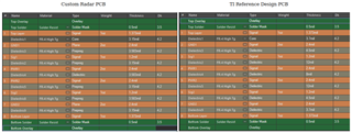
We designed a custom PCB with this chip and our PCB reports less points than the TI Eval board. If we change the Detection Threshold parameter to 10dB (versus 12dB on the Eval board) then we will get a similar amount of reported points.

But even with that adjustment, when we compare our board and the TI Eval board side by side, our PCB reports more erroneous points.

Is there anything specific that could cause this?


Thank you

-Matt

  • Hi Matt, 

    It sounds like your SNR is not as good on your custom PCB. There are a lot of things that could cause reduced performance.

    Did you follow the TI reference design exactly? Is your layout different? What is your PC stack up? Did you add any components to your board? Did you change your power supply? Did you modify the software?

    Regards,

    Luke.

  • I did a lot of the earlier work on the design that Matt is talking about. But we followed the main break away portion of the reference schematic exactly with the exception of removing the uart mux and usb to uart converter, and swapping the usb connector for a different one. No new components were added to the board. The layout is significantly different as we tried to make it a pretty compact board, but the power signals from the 4 channel regulator seem to be pretty clean (let me know if there are other things to check there).
    The Layer stackup of the board was changed (this is what our current theory is on why they perform differently). It seems like the space between the "Top Layer" and "GND1" are what should matter most. Would this change cause worse SNR on the custom PCB? Bellow is our custom layer stackup compared to the reference design.

  • Hi,

    Give me a little more time to look into this, I should get back to you by the end of the week or sooner.

    Regards,

    Luke

  • Hi Parker & Matt,

    I apologize for misunderstanding which device you are using. Being that you are using an AOP, then stackup and layout should not really matter (it only comes into play if you are designing a custom antenna pattern on a PCB).

    Power routing and xtal placement can certainly affect performance. I would recommend going to the mmWave Hardware Desgin Tool and select for AOP for more recommendations

    Regards,

    Luke

  • The Hardware Design Tool has a section that tells you to avoid placing any components in the Azimuth direction (above and below the chip).  We had unknowingly designed our board with the exact opposite orientation.  We are now going to rotate the chip 90 degrees to solve the problem.  Thanks for your help.