This thread has been locked.

If you have a related question, please click the "Ask a related question" button in the top right corner. The newly created question will be automatically linked to this question.

IWR6843ISK: Unusual X, Y, Z coordinates for Range

Part Number: IWR6843ISK

Hi There,

I’m using an IWR6843ISK to measure the falling velocity of a small object along the y-axis (directly away from the antennas).


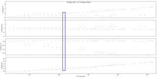
The radar seems to be returning the data in pairs, and the spatial coordinates of the second sample in each pair seems wrong. The reconstructed range looks correct however, even for the erroneous second sample.


Below is a plot showing the X, Y, Z and Range values against Time, with one such pair highlighted.

Why do you think this is happening?

I've also attached the cfg if that's relevant.5_2_2_2_profile_2023_02_08T04_16_25_725.cfg

Thanks,

Aston

  • Hi Aston, 

    I have a couple questions to help me better understand your situation:

    1. Are you running any of our example projects or the Out of Box demo for this experiment? If so, which example and which versions of the Toolbox and mmWave SDK are you using?
      1. What modifications, if any, have you made to the demo code?
    2. Is the code to plot the collected data developed by yourself? If so, have you seen our output data format guide and ensured that you are parsing the data correctly?
    3. To me it seems that you have the sensor mounted at some elevation facing directly towards the ground, then you are dropping items from directly below the sensor. Is that correct?

    Best Regards,

    Josh

  • Hi Josh,

    1. Yes this is running the Out of Box demo. It is using SDK ver 3.05 and was created on the online visualiser ver 3.5.0.0
           a. Only modification was to turn on clutter removal

    2. Yes the code for plotting is developed by myself. Yes, I have read that document (quite helpful once I found it), the code uses parsing functions from the TI-built python-based GUI, so I am reasonably confident that it should be parsing correctly.

    3. You are correct, for this plot the radar was placed approx 3.5m above the ground and the small objects were dropped from just behind the sensor down past it, aiming to be falling right next to broadside. The objects tend to stay approximately along the same axis as they fall, although they are spinning as they fall.

    Thanks,

    Aston

  • Hi Aston, 

    Thanks for the answers. 

    The radar seems to be returning the data in pairs

    I think you are referring to the detected points TLV, meaning there are multiple (2) points detected each frame. Is my understanding correct? 

    Though based on your plots it seems that for some frames only a single point is detected. How small is the object which you are dropping and what material is it composed of? I'm wondering if it is reasonable to expect your object to generate multiple points or if it's possible that the second detected point is caused by some unwanted reflection. 

    Can you tell me a bit more about your setup? Are you performing the experiment in a wide open space or with nearby walls? Is the radar mounted on the ceiling or similar structure or is it mounted using a tri-pod/stand which is present in the radar's FOV?

    Sorry for all the questions. 

    Best Regards,

    Josh

  • Hi Josh,

    think you are referring to the detected points TLV, meaning there are multiple (2) points detected each frame. Is my understanding correct? 

    No, I'm meaning if you look at the data within the blue box it seems to be paired in the range plot however there are significant differences between the x, y, z, coordinates of the two points.

    How small is the object which you are dropping and what material is it composed of?

    In this test I'm dropping Sycamore seeds, so I think it's unlikely there are multiple reflections. The seed bodies are about 8mm in x and y.

    Can you tell me a bit more about your setup

    This was performed toward the centre of a large room, think community hall, with the radar held off to the side at the top of an aluminium ladder by approx 1m. Yes, this would be within the field of view.

    Regards,

    Aston

  • Hi Aston,

    No, I'm meaning if you look at the data within the blue box it seems to be paired in the range plot however there are significant differences between the x, y, z, coordinates of the two points.

    Understood. I still would like to know what the pairs represent. How are you handling data for frames that contains multiple detected points?

    I think it's unlikely there are multiple reflections.

    Yes, you are correct. Based upon the size of the seeds we would not expect to see multiple points; however, I'm wondering if we are seeing the effects of some multipath reflection perhaps off the ladder etc...

    Is it possible for you to run the experiment again without the ladder? Or could you modify the aoaFovCfg command in the configuration file (.cfg) such that the portion of the radar's FOV which the ladder obscures is not included? This way any potential unwanted reflections should be filtered out. 

    Best Regards,

    Josh