Other Parts Discussed in Thread: MMWAVEICBOOST,
Hi,
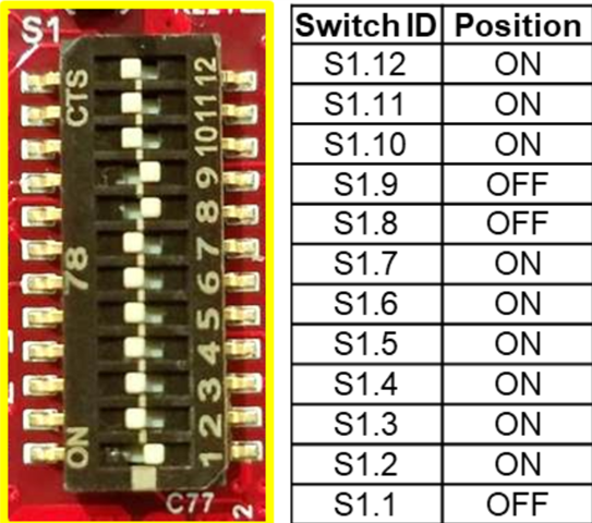
I flashed successfully the IWR6843ISK via MMWAVEICBOOST board.
I launched the vital sign demo but there are no data on the interface. Please se the Display prompt window:
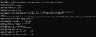
Please for help
Hi,
I flashed successfully the IWR6843ISK via MMWAVEICBOOST board.
I launched the vital sign demo but there are no data on the interface. Please se the Display prompt window:
Please for help