This thread has been locked.

If you have a related question, please click the "Ask a related question" button in the top right corner. The newly created question will be automatically linked to this question.

IWR1443: The setting of the source addresses of the ping and pong parameter sets in HWA

Part Number: IWR1443


Hi Team,

1. For the iwr1443 project in the low-power design scheme of level_sense_demo, the source address of the HWA parameter set of ping and pong is set to gMmwHwaMemBuf[0]. Why are the source addresses of the two not gMmwHwaMemBuf[0] or gMmwHwaMemBuf[1] respectively?

2. Is the DFE output mode in this project Single-chirp mode? If it is this mode, then the completion of the interrupts of ping and pong will trigger the processing of HWA parameter set. Then the source address should correspond to different buffers. Is my speculation correct?

3. When the project is actually debugged, gMmwHwaMemBuf[1](0x52034000) has no data, and the data of gMmwHwaMemBuf[0](0x52030000) is all full. Why is it full here? The project configuration is 2CHIRP, 1frame, 990 samples per CHIRP with 4 bytes per sample.

Kind regards,

Katherine

  • 5. I re-read the relevant configuration of ADCBUF, chirpThreshold=1, does this mean that DFE adopts multi-chirp mode? Secondly, I would like to know if the DFE trigger signal in HWA refers to the interrupt signal in the figure below? So under the configuration of this project, can only one interrupt signal be generated? However, the triggers of ping and pong in the HWA parameter set are all triggered by DFE.

  • Hi Katherine, 

    We are looking into your questions. You can expect a response tomorrow. 

    Best Regards,

    Josh

  • Hi Katherine,

    Please review these similar threads and programmer's guide. They should provide some of the information you are looking for.

    Best Regards,

    Josh

    https://e2e.ti.com/support/sensors-group/sensors/f/sensors-forum/1201917/iwr1843boost-iwr1843boost 

    https://e2e.ti.com/support/sensors-group/sensors/f/sensors-forum/1173826/iwr1843boost-iwr1843boost 

    https://www.ti.com/lit/pdf/swra555 

  • Can you answer my four questions directly? I don't think the relevant links you provided can help me determine the correct answer. I have already read the instruction manual before, and still have doubts about the storage addresses of ping and pong , and triggering HWA signals? The engineering configuration of this routine is 1 chirp, 2 numloops, 1 frame, 990samples, 4 bytes of sample data, and the chirpThreshold of ping and pong=1

  • Hello,

    I'm sorry that the resources I linked did not help. Please allow us some time to review your questions in detail. You can expect a response by the end of this week. 

    Best Regards,

    Josh

  • Please give me a reply

  • Hi, 

    Very sorry for the delay here. The engineer responsible for this demo has recently left so we are still trying to fully understand this code.

    It seems this demo is not using the typical ping/pong approach for HWA processing. From my understanding only a ping paramset exists in the HWA configuration. Where do you see a pong paramset which has a source address that is also set to gMmwHwaMemBuf[0]?

    Regards,

    Josh

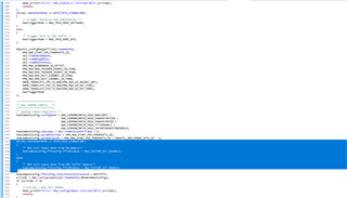
  • The following are the relevant functions related to HWA parameter configuration in the level_sense_demo project. The selected section (gray colour) is about the parameter configuration of pong. It can be seen that it reuses ping parameters, but only modifies the target address.

    void demo_config1D_HWA(Demo_DataPathObj *obj)
    {
    int32_t errCode;
    HWA_CommonConfig hwaCommonConfig;
    uint8_t hwaTriggerMode;

    /* Disable the HWA */
    errCode = HWA_enable(obj->hwaHandle,0); // set 1 to enable
    if (errCode != 0)
    {
    //retCode = HWA_TEST_ERROR;
    demo_printf("Error: HWA_enable(1) returned %d\n",errCode);
    return;
    }
    if(obj->dataPathMode == DATA_PATH_STANDALONE)
    {
    /* trigger manually and immediately */
    hwaTriggerMode = HWA_TRIG_MODE_SOFTWARE;
    }
    else
    {
    /* trigger done by ADC buffer */
    hwaTriggerMode = HWA_TRIG_MODE_DFE;
    }

    HWAutil_configRangeFFT(obj->hwaHandle,
    MMW_HWA_START_POS_PARAMSETS_1D,
    obj->numAdcSamples,
    obj->numRangeBins,
    obj->numRxAntennas,
    MMW_HWA_WINDOWRAM_1D_OFFSET,
    MMW_HWA_DMA_TRIGGER_SOURCE_1D_PING,
    MMW_HWA_DMA_TRIGGER_SOURCE_1D_PONG,
    MMW_HWA_DMA_DEST_CHANNEL_1D_PING,
    MMW_HWA_DMA_DEST_CHANNEL_1D_PONG,
    ADDR_TRANSLATE_CPU_TO_HWA(MMW_HWA_1D_ADCBUF_INP),
    ADDR_TRANSLATE_CPU_TO_HWA(MMW_HWA_1D_OUT_PING),
    ADDR_TRANSLATE_CPU_TO_HWA(MMW_HWA_1D_OUT_PONG),
    hwaTriggerMode
    );

    /***********************/
    /* HWA COMMON CONFIG */
    /***********************/
    /* Config Common Registers */
    hwaCommonConfig.configMask = HWA_COMMONCONFIG_MASK_NUMLOOPS |
    HWA_COMMONCONFIG_MASK_PARAMSTARTIDX |
    HWA_COMMONCONFIG_MASK_PARAMSTOPIDX |
    HWA_COMMONCONFIG_MASK_FFT1DENABLE |
    HWA_COMMONCONFIG_MASK_INTERFERENCETHRESHOLD;
    hwaCommonConfig.numLoops = obj->numChirpsPerFrame / 2;
    hwaCommonConfig.paramStartIdx = MMW_HWA_START_POS_PARAMSETS_1D;
    hwaCommonConfig.paramStopIdx = MMW_HWA_START_POS_PARAMSETS_1D + HWAUTIL_NUM_PARAM_SETS_1D - 1;
    if(obj->dataPathMode == DATA_PATH_STANDALONE)
    {
    /* HWA will input data from M0 memory*/
    hwaCommonConfig.fftConfig.fft1DEnable = HWA_FEATURE_BIT_DISABLE;
    }
    else
    {
    /* HWA will input data from ADC buffer memory*/
    hwaCommonConfig.fftConfig.fft1DEnable = HWA_FEATURE_BIT_ENABLE;
    }
    hwaCommonConfig.fftConfig.interferenceThreshold = 0xFFFFFF;
    errCode = HWA_configCommon(obj->hwaHandle,&hwaCommonConfig);
    if (errCode != 0)
    {
    //retCode = HWA_TEST_ERROR;
    demo_printf("Error: HWA_configCommon returned %d\n",errCode);
    return;
    }
    }


    void HWAutil_configRangeFFT(HWA_Handle handle,
    uint32_t paramSetStartIdx,
    uint32_t numAdcSamples,
    uint32_t numRangeBins,
    uint8_t numRxAnt,
    uint32_t windowOffsetBytes,

    uint8_t dmaTriggerSourcePing,
    uint8_t dmaTriggerSourcePong,

    uint8_t dmaDestChannelPing,
    uint8_t dmaDestChannelPong,

    uint16_t hwaMemAdcBufOffset,

    uint16_t hwaMemDestPingOffset,
    uint16_t hwaMemDestPongOffset,
    uint8_t hwaTriggerMode)
    {
    HWA_InterruptConfig paramISRConfig;
    int32_t errCode = 0;
    uint32_t paramsetIdx = paramSetStartIdx;
    uint32_t pingParamSetIdx = 0;
    HWA_ParamConfig hwaParamCfg[HWAUTIL_NUM_PARAM_SETS_1D];

    memset(hwaParamCfg,0,sizeof(hwaParamCfg));

    /***********************/
    /* PING DUMMY PARAMSET */
    /***********************/
    hwaParamCfg[paramsetIdx].triggerMode = HWA_TRIG_MODE_DMA; //Software triggered - in demo this will be HWA_TRIG_MODE_DMA
    hwaParamCfg[paramsetIdx].dmaTriggerSrc = dmaTriggerSourcePing; //in demo this will be first EDMA Src channel id
    hwaParamCfg[paramsetIdx].accelMode = HWA_ACCELMODE_NONE; //dummy
    errCode = HWA_configParamSet(handle,paramsetIdx,&hwaParamCfg[paramsetIdx],NULL);
    if (errCode != 0)
    {
    //retCode = HWA_TEST_ERROR;
    demo_printf("Error: HWA_configParamSet(%d) returned %d\n", paramsetIdx, errCode);
    return;
    }

    /***********************/
    /* PING PROCESS PARAMSET */
    /***********************/
    paramsetIdx++;
    pingParamSetIdx = paramsetIdx;
    hwaParamCfg[paramsetIdx].triggerMode = hwaTriggerMode;
    hwaParamCfg[paramsetIdx].accelMode = HWA_ACCELMODE_FFT; //do FFT

    hwaParamCfg[paramsetIdx].source.srcAddr = hwaMemAdcBufOffset; // address is relative to start of MEM0
    hwaParamCfg[paramsetIdx].source.srcAcnt = numAdcSamples - 1; //this is samples - 1
    hwaParamCfg[paramsetIdx].source.srcAIdx = numRxAnt * sizeof(uint32_t); // 16 bytes
    hwaParamCfg[paramsetIdx].source.srcBcnt = numRxAnt-1; //no iterations here
    hwaParamCfg[paramsetIdx].source.srcBIdx = sizeof(uint32_t); //should be dont care
    hwaParamCfg[paramsetIdx].source.srcShift = 0; //no shift
    hwaParamCfg[paramsetIdx].source.srcCircShiftWrap = 0; //no shift
    hwaParamCfg[paramsetIdx].source.srcRealComplex = HWA_SAMPLES_FORMAT_COMPLEX; //complex data
    hwaParamCfg[paramsetIdx].source.srcWidth = HWA_SAMPLES_WIDTH_16BIT; //16-bit
    hwaParamCfg[paramsetIdx].source.srcSign = HWA_SAMPLES_SIGNED; //signed
    hwaParamCfg[paramsetIdx].source.srcConjugate = 0; //no conjugate
    hwaParamCfg[paramsetIdx].source.srcScale = 8;
    hwaParamCfg[paramsetIdx].source.bpmEnable = 0; //bpm removal not enabled
    hwaParamCfg[paramsetIdx].source.bpmPhase = 0; //dont care

    hwaParamCfg[paramsetIdx].dest.dstAddr = hwaMemDestPingOffset; // address is relative to start of MEM0
    hwaParamCfg[paramsetIdx].dest.dstAcnt = numRangeBins-1; //this is samples - 1
    hwaParamCfg[paramsetIdx].dest.dstAIdx = numRxAnt * sizeof(uint32_t); //
    hwaParamCfg[paramsetIdx].dest.dstBIdx = sizeof(uint32_t); //should be dont care
    hwaParamCfg[paramsetIdx].dest.dstRealComplex = HWA_SAMPLES_FORMAT_COMPLEX; //same as input - complex
    hwaParamCfg[paramsetIdx].dest.dstWidth = HWA_SAMPLES_WIDTH_16BIT; //same as input - 16 bit
    hwaParamCfg[paramsetIdx].dest.dstSign = HWA_SAMPLES_SIGNED; //same as input - signed
    hwaParamCfg[paramsetIdx].dest.dstConjugate = 0; //no conjugate
    hwaParamCfg[paramsetIdx].dest.dstScale = 0;
    hwaParamCfg[paramsetIdx].dest.dstSkipInit = 0; // no skipping

    hwaParamCfg[paramsetIdx].accelModeArgs.fftMode.fftEn = 1;
    hwaParamCfg[paramsetIdx].accelModeArgs.fftMode.fftSize = log2Approx(numRangeBins);
    hwaParamCfg[paramsetIdx].accelModeArgs.fftMode.butterflyScaling = 0x3; //LSB fftSize bits are relevant - revisit this for all FFT size and data size
    hwaParamCfg[paramsetIdx].accelModeArgs.fftMode.interfZeroOutEn = 0; //disabled
    hwaParamCfg[paramsetIdx].accelModeArgs.fftMode.windowEn = 1; //enabled
    hwaParamCfg[paramsetIdx].accelModeArgs.fftMode.windowStart = windowOffsetBytes; //start of window RAM
    hwaParamCfg[paramsetIdx].accelModeArgs.fftMode.winSymm = 1; //symmetric - in demo do we make this symmetric
    hwaParamCfg[paramsetIdx].accelModeArgs.fftMode.winInterpolateMode = 0; //fftsize is less than 1K
    hwaParamCfg[paramsetIdx].accelModeArgs.fftMode.magLogEn = HWA_FFT_MODE_MAGNITUDE_LOG2_DISABLED; //disabled
    hwaParamCfg[paramsetIdx].accelModeArgs.fftMode.fftOutMode = HWA_FFT_MODE_OUTPUT_DEFAULT; // output FFT samples

    hwaParamCfg[paramsetIdx].complexMultiply.mode = HWA_COMPLEX_MULTIPLY_MODE_DISABLE;
    errCode = HWA_configParamSet(handle,paramsetIdx,&hwaParamCfg[paramsetIdx],NULL);
    if (errCode != 0)
    {
    //retCode = HWA_TEST_ERROR;
    demo_printf("Error: HWA_configParamSet(%d) returned %d\n",errCode,paramsetIdx);
    return;
    }
    /* enable the DMA hookup to this paramset so that data gets copied out */
    paramISRConfig.interruptTypeFlag = HWA_PARAMDONE_INTERRUPT_TYPE_DMA;
    paramISRConfig.dma.dstChannel = dmaDestChannelPing; //TODO sync this define EDMA channel to trigger to copy the data out
    //paramISRConfig.cpu.callbackArg = paramSetSem;//TODO check if NULL is required
    errCode = HWA_enableParamSetInterrupt(handle,paramsetIdx,&paramISRConfig);
    if (errCode != 0)
    {
    //retCode = HWA_TEST_ERROR;
    demo_printf("Error: HWA_enableParamSetInterrupt(PING DMA) returned %d\n",errCode);
    return;
    }

    /***********************/
    /* PONG DUMMY PARAMSET */
    /***********************/
    paramsetIdx++;
    hwaParamCfg[paramsetIdx].triggerMode = HWA_TRIG_MODE_DMA;
    hwaParamCfg[paramsetIdx].dmaTriggerSrc = dmaTriggerSourcePong; //in demo this will be second EDMA Src channel id
    hwaParamCfg[paramsetIdx].accelMode = HWA_ACCELMODE_NONE; //dummy
    errCode = HWA_configParamSet(handle,paramsetIdx,&hwaParamCfg[paramsetIdx],NULL);
    if (errCode != 0)
    {
    //retCode = HWA_TEST_ERROR;
    demo_printf("Error: HWA_configParamSet(%d) returned %d\n",errCode,paramsetIdx);
    return;
    }

    /***********************/
    /* PONG PROCESS PARAMSET */
    /***********************/
    paramsetIdx++;
    hwaParamCfg[paramsetIdx] = hwaParamCfg[pingParamSetIdx];
    hwaParamCfg[paramsetIdx].dest.dstAddr = hwaMemDestPongOffset;
    errCode = HWA_configParamSet(handle,paramsetIdx,&hwaParamCfg[paramsetIdx],NULL);
    if (errCode != 0)
    {
    //retCode = HWA_TEST_ERROR;
    demo_printf("Error: HWA_configParamSet(%d) returned %d\n",errCode,paramsetIdx);
    return;
    }
    /* enable the DMA hookup to this paramset so that data gets copied out */
    paramISRConfig.interruptTypeFlag = HWA_PARAMDONE_INTERRUPT_TYPE_DMA;
    paramISRConfig.dma.dstChannel = dmaDestChannelPong;
    //paramISRConfig.cpu.callbackArg = paramSetSem;//TODO check if NULL is required
    errCode = HWA_enableParamSetInterrupt(handle,paramsetIdx,&paramISRConfig);
    if (errCode != 0)
    {
    //retCode = HWA_TEST_ERROR;
    demo_printf("Error: HWA_enableParamSetInterrupt(PING DMA) returned %d\n",errCode);
    return;
    }
    }

  • Hi, 

    Thank you for pointing out the relevant code. Just to confirm we are looking at the same example project, can you let me know which version of the Toolbox you are using?

    Regards,

    Josh

  • This project can be downloaded by clicking on the software at the following website.

    TIDEP-0091 reference design | TI.com

    After decompressing the downloaded file, you can import the iwr1443 project from the file through CCS.

    The tool version used for this project is as follows

    XDC tools 3.50.4.43

    SYS/BIOS 6.53.2.00

    mmWave SDK 2.1.0.04

    Please reply to me as soon as possible, thank you!

  • Hello, 

    Ah, I understand now. I had not realized you were referring to this reference design instead of the level sensing demo in the Radar Toolbox, my apologies. I'm investigating your queries now and will get back to you. You can ping this thread if I do not respond within 24 hours. 

    Best Regards,

    Josh 

  • Please give me a replay, Thank you

  • Hello, 

    After reviewing the code I'm inclined to agree with you. It seems that under this HWA configuration the same processing is being done on the same data for ping and pong. I am trying to confirm this through debugging. 

    When the project is actually debugged, gMmwHwaMemBuf[1](0x52034000) has no data, and the data of gMmwHwaMemBuf[0](0x52030000) is all full. Why is it full here? The project configuration is 2CHIRP, 1frame, 990 samples per CHIRP with 4 bytes per sample.

    Can you please let me know where you have placed a breakpoint? I agree based on the expected size of the data it should not be full. I will try to debug the same on my end. 

    chirpThreshold=1, does this mean that DFE adopts multi-chirp mode? Secondly, I would like to know if the DFE trigger signal in HWA refers to the interrupt signal in the figure below?

    With chirpThreshold=1 an this means that after 1 chirp the ping/pong buffer will switch. The interrupt signal in the figure you have shown is generated every time the buffer switches and yes it does in turn trigger the HWA. 

    Regards,

    Josh

  • I set the breakpoint after HWA processed the data. According to the ping and pong processing methods, M0 and M1 should contain ADC data for chirp 1 and chirp 2 respectively, and M2 and M3 should contain corresponding FFT data. Currently, it shows that M0 has too much data, M1 has no data, and M2 and M3 seem normal.

    Please give me a replay, Thank you

  • Hello, 

    I have not yet been able to replicate this on my end. 

    Please allow me some time to step through the code and investigate your findings. You can expect a response within 48hrs. Very sorry for the delay here, your patience is appreciated. 

    Best Regards,

    Josh

  • Please give me a replay, Thank you

  • Hello, 

    I have been able to debug this on my setup. I can confirm that I see the same result as you. M0 appears that it is full; however, this only appears to be the case because the memory is never initialized to 0. Each time this is filled it should only be filling up 3960 bytes (990 samples * 4bytes each). If you watch closely using the memory browser around the address 0x52030000 + 0xF76 (0xF76 equating to 3960 bytes), you can see that the addresses past this are not being updated. 

    As for why the source address is the same for both ping and pong processing; for this device, the ADC switch between PING and PONG is seamless to the application which always reads ADC data at the same address (ADC buffer address). This can be seen in Figure 2. of the Datapath Programmer's Guide.

    Best Regards,

    Josh 

  • In this project, after processing a frame of data by HWA, configure the FFT1DEN of State Machine Registers in HWA to 0 and enable HWA, and it will be seen that ADC data exists in both M0 and M1. It seems that in non shared mode, ADC data in M1 will be visible; In shared mode, the ADC data in M1 is displayed as 0. And the calculation result after changing the FFT src address of pong in the first frame HWA unit to M1 is also 0, which verifies that there is no ADC data in M1 in shared mode. So the question becomes, how did the ADC data in M1 come from after disabling FFT1DEN?

  • Please give me a replay, Thank you

  • Hello, 

    The FFT1DEN register is documented in the HWA User Guide

    I suggest you also read section 1.1.2.1 High-Level Data Flow of this guide which explains the sharing of data between ADC Buffer / HWA memory. 

    Regards,

    Josh

  • What I want to express is that in shared mode, M0 and M1 serve as buffers for PING and PONG. In fact, there is ADC data in M0 and M1. So why should the FFT source address of PONG be set to M0? Is there a contradiction in this design, or is it necessary for some reason?

  • Please give me a replay, Thank you

  • Hello, 

    In shared mode the switching of ping and pong buffer access is handled automatically and the application need only read the data from a single location hence why the source address is set to M0 for both ping and pong. In non-shared mode this would not be the case and data would need to be read from each location independently. 

    Regards,

    Josh