This thread has been locked.

If you have a related question, please click the "Ask a related question" button in the top right corner. The newly created question will be automatically linked to this question.

IWR6843: Variability in performance

Part Number: IWR6843

Hi,

I have recently had a design manufactured which incorporated the IWR6843 with the patch antenna from the ISK Dev kit.

There are several changes in my design compared to the ISK dev kit, predominantly in power supply where independent buck converters were implemented with independent LDO regulators to supply all rails (3V3, 1V8, 1V2 and 1V0) to reduce noise.

The design closely follows the stack up from the ISK dev kit, including ENiAg finish and the PCBs were manufactured with IPC class three tolerance. Dielectric 1 (Rogers Material) was RO4835Lo Pro with 1/1 RA copper plated to 1.6mil on the top layer. The other layers were equivalent PCL370HR material, but in marginally different thicknesses from the ISK dev kit.

A batch of 50 units were made and tested using the standard 14m configuration that was provided with the ISK dev kit.
The sensors were mounted on the roof, and have tilt downward from the roof and are housed in tooled enclosures. Test were repeated with/without enclosures and results were identical.

Approximately 50% of these units were capable of detecting human targets at approximately 8-9m from the sensor when walking down the boresight towards the sensor. Also, these sensors were able to detect targets when moving in an arc with radii of 8-9m from the sensor once the targets entered the FOV (roughly +/-30-40 degrees from Boresight). All sensors could track targets (after detection within 0-8m) up till approximately 10m. These units are our high performers and are satisfactory to our goals.

Approximately 25% of these units were capable of detecting targets at 5-6m from the sensor when walking down the boresight towards the sensor. Also, these sensors were able to detect targets when moving in an arc with radii of 5-6m from the sensor once the targets entered the FOV (roughly +/-30-40 degrees from Boresight). All sensors could track targets (after detection within 0-5m) up till approximately 9-10m.These units are low performers and are minimally effective for our application.

Approximately 25% of these units were capable of detecting targets up to 4m from the sensor when walking down the boresight towards the sensor. Also, these sensors were able to detect targets when moving in an arc with radii of <4m from the sensor once the targets entered the FOV (roughly +/-30-40 degrees from Boresight). All sensors could track targets (after detection within <4m) up till approximately 8m. These units are not effective for our application.

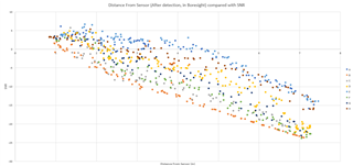
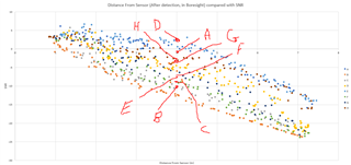
We have looked into the average SNR for each target for the sensors, and although there is a clear trend in distance to SNR there is no significant difference in sensors which can detect from 0-4m to 0-8m.
The SNR tests were performed with trihedral corner reflectors at multiple distances down the sensors boresight.

The tracking seems to be effective, but the variability of the detection is my concern.

Previous manufactured designs had low performance detection, so in this current design we went to IPC Class 3, and used 1/1RA copper with ENiAg to match the ISK dev kit.
Using corner reflectors I can manually test the detection area, but I cannot seem to find a way to gauge the detection area based on the SNR or other metric from the IWR6843.

Is there any diagnostic information available to the IWR6843 that describes the antenna performance, detection area or other descriptive measure for estimated performance, or am I missing a calibration step which might improve the detection FOV?

Side note, higher temperature reflow of the IWR6843 does not improvethe detection performance. Swapping power circuitry with high performer's parts also has no appreciable effect on detection performance.

Thanks in advance
Matthew

  • Hi Matthew,

    This is a very interesting question. Thank you for all the background. I will start by saying that we should decouple the SNR of a corner reflector from the tracking distance performance for now, as these may be 2 separate issues and will help the debug.

    For the HW performance, it is best to test a static repeatable test like it seems you have. Do you have actual data on the SNR of the CR you can share? You say there is no significant difference between the boards but this could be subtle. If you have tested the different performance boards with CR at different distances and measured the difference please post the numbers. Even a small but constant delta could cause this change in performance. I would also ask that you do the measurements at higher angles as well. It could be possible that the boresight power is similar, but the FOV performance varies due to board tolerances. 

    In general there is no internal test mechanism in the IWR6843 to test the antenna pattern. You will need to measure the SNR performance of a CR as you rotate the board to test the antenna FOV. I do recommend you perform this test with any new batch of boards you get (if there are fab changes) to verify antenna performance.

    For the human target detection, can you please let me know which demo and configuration file you are using to test? Are you looking at the tracking output from people counting or just the pointcloud output from one of the demos? Pointcloud detection should be very closely corelated with the SNR from the CR, but there are a lot more SW settings if you are using tracking to determine your detection. Further, human motion in difficult to repeat exactly so if you are at a performance boundary you may see a variability in this. The exact SW and chirp configuration will help to understand what performance should be expected.

    Finally, if you do this human detection test with the TI IWR6843ISK EVM and use the same SW, what are the results? And if you have a few more details about the test setup (mounting height of the roof, approximate tilt angle) it would be helpful.

    Thanks,

    Jackson

  • Hi Jackson,

    Thanks for the reply.

    For the CR it is handmade, so no there is no specific data for it, I can provide the measurements for the sides if that would help. 

    I agree it would be a subtle difference in the manufactured board that is causing this issue, but from a hardware perspective it is hard to control all critical elements (Impedance, trace width, copper thickness, geometry) to a higher degree than the current manufacture. I thought IPC3 would have been a solution to previous revisions, especially considering the ISK Dev kit is only IPC2.

    For detection I am looking specifically at detection only, not the point cloud. My end application cannot support the point cloud information output.

    I am careful to disambiguate detection and tracking, as the results are clearly different by design.

    For example, the following figure represents 8 Sensors (A-H) in tracking performance. Whereby the sensor was allowed to form a track, then the SNR was saved and compared to the distance, with the target walking up and down the boresight.


    To note, SNR here is calculated as the mean of the SNR readings reported for the target. Then this mean is multiplied by 10 to return the 0.1 steps back to their dBm value. Finally I added a minus sign, as the SNR values were increasing as distance got larger which is opposite to what should occur. 

    Hence, SNR = -10*Mean(target's point cloud SNR values). 

    From the above graph I was expecting to be able to predict detection area as there would be lower limit for the sensor to detect targets based on the SNR as provided in the config file. But unexpectedly, this was not the case.

    To test detection area a grid was setup whereby a human would walk the grid (Left to Right), from outside the possible FOV then walk along the grid until they were no longer detected then re-enter at the next increment (1m further away). The furthest distance (only in Y dimension/boresight) was identified as the detection distance. This is because if at the edge of the sensors FOV, say -4,3m (far to left of the sensor, 3m forward) then the sensor would almost always detect targets at any lessor angle, for example -2,3m.

    For the same sensors in the above figure the detection distances (given as only Y distance, distance down the boresight) are as follows

    A B C D E F G H
    3.38 6.62 3.21 4.54 5.67 6.85 6.9 7.07

    As indicated, B, F, G, H are higher performers with detection >6m
    D, E 4-6m
    A, C < 4m

    Strangely, the SNR values in the figure above suggest that C (Grey dots) would be a high performer as it has SNR readings (during the tracking test) just below B, and above F and G.

    A RC was then placed at 3m directly in the boresight. The RC was placed on a device to maintain a small constant rocking motion to emulate movement. 
    The SNR, and X/Y distances was recorded for ~30-60 seconds for each sensor. 

    A B C D E F G H
    X 0.164651 0.044833 0.044211 0.370508 0.097333 0.03589 0.308905 -0.18921
    Y 3.097442 3.078667 2.980526 3.144576 3.289 3.357246 3.355109 3.204532
    SNR 0.081395 -10.235 -8.51053 2.827119 -7.34 -7.07076 -4.18467 -3.70719

    On the original graph used for tracking these SNR reading look like this:

    Most of the sensors RC readings at 3m matched their trends from tracking. D however was vastly different.

    Happy to send you the configuration file used in an email along with hardware details, elevation, angle etc.

    Based on my findings, the SNR value is not effective at estimating the detection area, and the only real option is a series of CR's. But this does not form a measurement to identify where this variability comes from or why simply some sensors are better than others. 

    Thanks in advance
    Matthew


  • Hi Matthew, sorry for the delay. Based on these findings it does seem to be a board to board variation likely causing the issues, likely not a SW issue.

    However, it may still be beneficial to measure the static, or 0 doppler, response of the corner reflector with each of the boards. Your test was good since it should be perfectly repeatable, but I would still want to isolate any extra variables in the test (ie motion). To do this you should be able to enable static detections if using the 3D people counting demo binary, or you can use the out of box demo to test.

    Also linked below is a production test doc that goes through some other checks of new HW.

    It may also be required to calibrate the antenna differences. There is some discussion of it in the link below. Or a full procedure can be found in the overhead 3D people counting user's guide (pre-req 3).
    https://www.ti.com/lit/an/spracx7/spracx7.pdf 
    https://dev.ti.com/tirex/explore/node?a=1AslXXD__1.00.00.26&a=VLyFKFf__4.12.1&node=A__AOWuF2v3eDFHAsxFXhvtzQ__radar_toolbox__1AslXXD__1.00.00.26 

    Regards,

    Jackson