


Hi team,
Here's an issue from the customer may need your help:
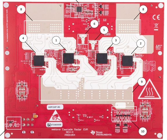
The antenna layout is shown in the figure below, with 4, 1, 3, 2 from left to right chip:
The default configuration when configured using the mmWave studio lua script is shown in the following figure:
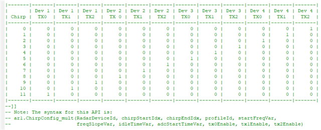
1) As described above, data should be sent from left to right (4-chip transmission skips 1 chip, 1-chip transmission last).
Assuming only 12 chirps are sent, are the first 9 chirps of receive antenna 1-16 the chirp (chips 4-2) sent from the horizontal antenna? The next 10-12 chirps are the chirp data sent by the tilt antenna (chip 1)?
2) Please see the following figure when receiving data using a routine's function:
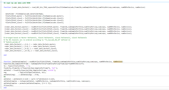
Is master the data received on the four receive antennas of chip 1? And is the slave2, 3, 4 corresponding to the data received on chip 2, 3, 4, respectively?
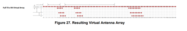
Should the virtual antenna layout be arranged in the order of slave4, slave3, slave2?
Also the customer sees a virtual receive antenna with the same phase overlap, how to select in this case?
Could you help check this case? Thanks.
Best Regards,
Cherry
