This thread has been locked.

If you have a related question, please click the "Ask a related question" button in the top right corner. The newly created question will be automatically linked to this question.

IWR6843AOP: tracking parameters for small rooms

Part Number: IWR6843AOP

Hi expert,

We find two strange phenomena when testing the People Counting Overhead project with the following config:

boundaryBox -2.00 1.90 -1.27 1.53 0.00 2.20
presenceBoundaryBox -1.50 1.40 -0.77 1.03 0.00 2.20
sensorPosition 2.17 0.0 90.0
gatingParam 3.0 1.5 1.5 2.0 4.0
stateParam 3 3 6 20 3 1000
allocationParam 60.0 40.0 0.05 40 1.5 20.0
maxAcceleration 1.0 0.1 1.0
trackingCfg 1 4 400 10 37 36 100 1


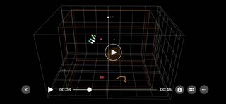
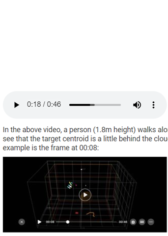
One is that the centroid is not output when walking across the sensor boresight. Sometimes, a new target is generated and the old one disappears.

We tested different values for bore sight filtering in trackingCfg and failed without luck. Would you please give some advices about how to avoid this?

In addition, I would like know why 0.1 is used for y-axis for the ceil mounting configuration in maxAcceleration. We also tested with a larger value 1.0 and also failed.

Thanks.

  • We tested different values for bore sight filtering in trackingCfg and failed without luck. Would you please give some advices about how to avoid this?

    The only values that should be tested here are 0 and 1, (it's an enable/disable). Did you try those?

    In addition, I would like know why 0.1 is used for y-axis for the ceil mounting configuration in maxAcceleration. We also tested with a larger value 1.0 and also failed.

    I am investigating this. I think in the ceiling mount case the x and y directions should be treated the same, so you can use the value of 1.

    If you have video to share with us of this failure case it would be helpful for further debugging.

    Best,

    Nate

  • We tested different values for bore sight filtering in trackingCfg and failed without luck. Would you please give some advices about how to avoid this?

    Yes, we tried both of them。

    I am investigating this. I think in the ceiling mount case the x and y directions should be treated the same, so you can use the value of 1

    Yes, that is why we use 1.0 in the test. 0.1 should be used for z-axis for the ceil mounting case and we will test it later.  I'll try that later.

    If you have video to share with us of this failure case it would be helpful for further debugging.

     I'll try that later.

    Thanks for your quick response.

    Best,

    Tony

  • Hi Nate,

    This is the video tha we talked about.

    In the above video, a person (1.8m height) walks along with the x-axis back and forward and keeps as steady as possible during the wall. We can see that the target centroid is a little behind the cloud points generated by the person and the target is not output when crossing the boresight. An example is the frame at 00:08:

    Thanks,

    Tony

  • Hi Tony, 

    I cannot play the video you have linked below. Can you make sure it's in an MP4 or another common video file format?

    Best,

    Nate

  • Hi Nate,

    it should be in MP4 format and you may be able to play it after downloading. To double check, I converted a new file and hope it works for you

    Best,

    Tony

  • Hi Tony,

    Why is your pointsThre set so high to 40? 40 points per track in a 2.17 m high overhead radar may be too many. Have you tried using one of the configuration files provided in the toolbox as a starting point?

    Best,

    Nate

  • Hi Nate,

    The targeting scene is the small bathroom in which there are a large number of reflected points from walls and the floor. We set 40 points to reduce ghosts.

    Any suggestions for such scenarios are really appreciated.

    Thinks.

    Best,

    Tony

  • Actually, we started with 20 points for target allocation and it did not work as well.

  • Hi Tony,

    Can you describe what the spheres and the cubes indicate in your video? I'm not quite sure what I'm looking at here. I surmise the multi-colored dots are the point cloud, but what about the orange and yellow spheres, as well as the boxes? 

    Can you also please send the entire configuration used?

    Best,

    Nate

  • Hi Nate,

    The cube presents boundary boxes defined for tracker, presence, static and dynamic respectively; the sphere represents the centroid of a target; the grid (0.5m internal space) represents walls and the floor; and 8 frames of points are accumulated and tinted in different colors. In addition, the color of a cube will be changed after a new target is reported from radar, along its trajectory on the ground.

    We use AOP and the People Counting Overhead project to do the test. Here is the full configuration:
    sensorStop
    flushCfg
    dfeDataOutputMode 1
    channelCfg 15 7 0
    adcCfg 2 1
    adcbufCfg -1 0 1 1 1
    lowPower 0 0
    profileCfg 0 61.2 60.00 17.00 50 328965 0 55.27 1 64 2000.0 2 1 36
    chirpCfg 0 0 0 0 0 0 0 1
    chirpCfg 1 1 0 0 0 0 0 6
    chirpCfg 2 2 0 0 0 0 0 6
    bpmCfg -1 1 1 2
    frameCfg 0 2 100 0 100 1 0
    fineMotionCfg -1 1 2.0 10 2
    dynamicRACfarCfg -1 4 4 1 1 8 8 6 4 15.0 15.0 0.5 1.0 1
    staticRACfarCfg -1 4 10 2 2 8 16 4 6 6.0 13.0 0.50 0.0 0
    dynamicRangeAngleCfg -1 7.000 0.0010 2 0
    dynamic2DAngleCfg -1 5 1 1 1.00 15.00 2
    staticRangeAngleCfg -1 0 1 1
    antGeometry0 -1 -1 0 0 -3 -3 -2 -2 -1 -1 0 0
    antGeometry1 -1 0 -1 0 -3 -2 -3 -2 -3 -2 -3 -2
    antPhaseRot 1 -1 1 -1 1 -1 1 -1 1 -1 1 -1
    fovCfg -1 64.0 64.0
    compRangeBiasAndRxChanPhase 0 0.49326 0.35260 -0.51355 -0.32175 0.53311 0.14481 -0.52194 -0.05939 0.46585 0.58429 -0.46326 -0.88623 0.37299 0.85580 -0.29562 -0.67081 0.27469 0.54504 -0.33862 -0.51828 0.42233 0.41248 -0.42822 -0.34235
    staticBoundaryBox -1.40 1.30 -0.67 0.93 0.00 2.20
    boundaryBox -2.00 1.90 -1.27 1.53 0.00 2.20
    presenceBoundaryBox -1.50 1.40 -0.77 1.03 0.00 2.20
    sensorPosition 2.17 0.0 90.0
    gatingParam 3.0 1.5 1.5 2.0 4.0
    stateParam 3 3 6 20 3 1000
    allocationParam 60.0 40.0 0.05 40 1.5 20.0
    maxAcceleration 1.0 1.0 1.0
    trackingCfg 1 4 400 10 37 36 100 1
    sensorStart

    We even reduced the tx power to the minimum for such small room, and also a couple of combinations of tx power and cfar thresholds, nothing helped.

    Thanks.

    Best,

    Tony

  • Hi Tony,

    Can you try using a default configuration provided in the toolbox? You may make the change to the max acceleration line of 

    maxAcceleration 1.0 1.0 1.0

    You may also increase the TX Backoff as I see you have done, but otherwise, please keep all the parameters the same, and tell me if you still see this error.

    Typically, if there are too many points from multi-path reflections, I would suggest increasing the TX Backoff and CFAR threshold values, rather than increase the number of points needed to allocate a track. 

    Best,

    Nate

  • Hi Nate,

    Thanks for your help and we will try that.

    Best,

    Tony