This thread has been locked.

If you have a related question, please click the "Ask a related question" button in the top right corner. The newly created question will be automatically linked to this question.

TMP401: TMP401

Part Number: TMP401

Hi,

I'm working on custom board that has TMP401 temperature sensor connected via I2C.

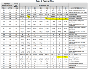
I have embedded linux installed on my board that utilises "tmp401.c" driver. 

The temperature is sampled correctly without any problems.

The issue i'm struggling with is regarding to the sample time.

From measurements i made it takes about 14[ms] to get the result from the sensor.

When i dived down to datasheet i discovered a cool feature that called "High speed mode" , that can works in 2.5[MHz].

I didn't yet figured out how to use this mode and how should i use it.

In the datasheet is mentioned to send through the I2C bus the following master code :"0x0000 1xxx" , but the context is missing for example:

To which register i should write the value, what is the sequence when using this mode.

Thanks for granted,

nati

  • nati,

    The I2C host must support High Speed (HS) Mode. If it supports this mode, it should prepend the master code to HS transactions that it makes, as appropriate. From a user perspective, you won't be able to add or enable this feature if it does not already exist. It relies on hardware and bus driver support. 

    At any rate, the 14ms is caused by the system latency and not by the bus speed. See Figure 14 in the TMP401 datasheet. There is about 9*5 clock cycles per register read. If both local and remote temperatures are read, this is 9*5*2 clock cycles. Your I2C bus is most likely operating at 400kHz, but it could be 100kHz. Even if operating at 100kHz, the two temperature read transactions only take 1/100,000*9*5*2 = 0.9ms. If you could enable HS mode and operate the bus at 2MHz, it would become 0.045ms. In either case, it would likely still take the system 13ms to do whatever else it is doing for overhead.

    thanks,

    ren

  • Hi ren,

    Thanks for your very detailed answer. 

    I fully understand your answer but something that still confusing me is Table 5 in datasheet , which describes typical conversion time in respect to resolution. Lets say i picked resolution of 9 bits , so according to Table 5 the typical conversion time is 12.5 [ms].                                                          This is very far from the conversion time according to your calculation.                                                                                                                                 How can you explain the gap between your calculation to the conversion time described in datasheet (Table 5)?   

    thanks,

    nati

  • I2C activity and internal activity (Table 5) are different clock domains. The TMP401 has an internal oscillator that it uses to run its ADC and digital state machine. It spends its time making temperature measurements or waiting according to the settings SD, R#, and RES#.

    Table 5 describes the default local conversion time as 12.5ms. This is how long it takes to measure the local temperature. The TMP401 must also measure remote temperature, and the ADC is shared for local and remote channels. The remote measurement is not configurable, and always takes 115ms. There is no setting to disable local or remote measurements. This means you will only be able to see one new local temperature measurement every 12.5+115ms. The result may not change for every measurement, making it difficult to discern whether the measurement occurred. 

    Looking back to our previous discussion, there are effectively three clock domains in play. The rate at which your computer performs I2C transactions is polling rate and not indicative of bus speeds achieved. The I2C bus has its own frequency that the transactions occur at. Finally, the TMP401 has its own internal rate that it operates at. 

    thanks,

    ren