This thread has been locked.

If you have a related question, please click the "Ask a related question" button in the top right corner. The newly created question will be automatically linked to this question.

IWR6843AOPEVM: Micro Doppler map different when extracted from raw data

Part Number: IWR6843AOPEVM

Dear,

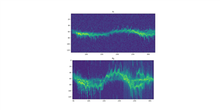
I am using the iwr6843aopevm radar in two ways. The first one is by collecting the raw data with the DCA board and mmwaveboost card, and then I have a python code to process that  data and get the the micro doppler map.

I also use the out of box demo in which I added some code to get micro doppler map by using the detection matrix. The image below shows the results of both pipelines, the spectrums are a bit different in terms of energy in higher doppler bins. 

What does not make sense is that the same configuration is used. Could you please give any hints what could make the difference?

Would this be related to the fact that using MMwaveIC Boost card gives better quality of signal?

Best regards,

Reda

  • Hi Reda,

    I don't think there should be a difference in the quality of the signal acquired. I think it's likely the difference is in your processing. Can you describe what your code does in greater detail and give more description to the graphs? I'm not sure what I'm looking at here.

    Best,

    Nate

  • Thank you for your response, for the python processing, basically I am applying a 1D FFT to get the range bins; then do clutter removal, afterwadrs I apply the Doppler FFT to get a range doppler map corresponding to each virtual antenna. Then I apply non coherent integration which gives me finally the detection matrix (Range Doppler Map). I apply a sum operator over range axis corresponding to each Doppler bin, to end up with a single vector of Doppler bins. 

    I apply the same operation again for each new coming frame, and then get the Micro Doppler map.

    For the C code, I use the OOB demo; where instead of sending the noiseProfile, I send the Doppler vector computed with this code; I added this portion of code:

            for(index = 0; index < subFrameCfg->numDopplerBins; index++)
            {
                tmp = 0;
                //check if Doppler bin zero being maxDopIdx = subFrameCfg->numDopplerBins/2 -1 needs to be in the sum or not
                for(index2 = 0; index2 < subFrameCfg->numRangeBins; index2++){
                    tmp += (n1*(uint32_t)detMatrix[index2*subFrameCfg->numDopplerBins + index]/n2);
                }
                final_temp = (uint16_t)((n2 * tmp)/(n1*(uint32_t)subFrameCfg->numRangeBins));
    

    What you see on the plots is two micro Doppler maps, the Y axis shows the Doppler bins, and the X axis shows the frame number.  The upper one was calculated with TI OOB demo, and the lower with Python. Its a recording of the same person walking in front of the radar.

    These are the parameters used for the configuraion of the radar when used  :


    % ***************************************************************
    sensorStop
    resetDevice
    flushCfg
    dfeDataOutputMode 1
    % dec2bin: 15= 1111, 7=111, 3=11, 1=1
    channelCfg 15 3 0
    adcCfg 2 1
    adcbufCfg -1 0 1 1 1
    %
    profileCfg 0 60 100 6 50 0 0 80 0 256 6000 0 0 30
    chirpCfg 0 0 0 0 0 0 0 1
    %this chirp is redundant?
    chirpCfg 1 1 0 0 0 0 0 0
    % max chrip/loop supported is 32 and frame period of 250
    frameCfg 0 0 100 0 50 1 0
    %
    lowPower 0 0
    %
    % guiMonitor [subFrameIdx][detected objects][log magnitude range]..
    %[noise profile][range(angle)HeatMap][rangeDopplerHeatMap][statsInfo>]
    guiMonitor -1 0 0 1 0 0 0
    %
    for the radar with mmwave boost board, this is the mmwave file:
    {
    "configGenerator": {
    "createdBy": "mmWaveStudio",
    "createdOn": "2021-05-27T11:44:47.8758272+02:00",
    "isConfigIntermediate": 1
    },
    "currentVersion": {
    "jsonCfgVersion": {
    "major": 0,
    "minor": 4,
    "patch": 0
    },
    "DFPVersion": {
    "major": 1,
    "minor": 2,
    "patch": 0
    },
    "SDKVersion": {
    "major": 3,
    "minor": 0,
    "patch": 0
    },
    "mmwavelinkVersion": {
    "major": 1,
    "minor": 2,
    "patch": 0
    }
    },
    "lastBackwardCompatibleVersion": {
    "DFPVersion": {
    "major": 1,
    "minor": 1,
    "patch": 0
    },
    "SDKVersion": {
    "major": 2,
    "minor": 0,
    "patch": 0
    },
    "mmwavelinkVersion": {
    "major": 1,
    "minor": 1,
    "patch": 0
    }
    },
    "regulatoryRestrictions": {
    "frequencyRangeBegin_GHz": 77,
    "frequencyRangeEnd_GHz": 81,
    "maxBandwidthAllowed_MHz": 4000,
    "maxTransmitPowerAllowed_dBm": 12
    },
    "systemConfig": {
    "summary": "This is a comments field not passed to device",
    "sceneParameters": {
    "ambientTemperature_degC": 20,
    "maxDetectableRange_m": 10,
    "rangeResolution_cm": 5,
    "maxVelocity_kmph": 26,
    "velocityResolution_kmph": 2,
    "measurementRate": 10,
    "typicalDetectedObjectRCS": 1
    }
    },
    "mmWaveDevices": [
    {
    "mmWaveDeviceId": 0,
    "rfConfig": {
    "waveformType": "legacyFrameChirp",
    "MIMOScheme": "TDM",
    "rlCalibrationDataFile": "",
    "rlChanCfg_t": {
    "rxChannelEn": "0xF",
    "txChannelEn": "0x7",
    "cascading": 0,
    "cascadingPinoutCfg": "0x0"
    },
    "rlAdcOutCfg_t": {
    "fmt": {
    "b2AdcBits": 2,
    "b8FullScaleReducFctr": 0,
    "b2AdcOutFmt": 1
    }
    },
    "rlLowPowerModeCfg_t": {
    "lpAdcMode": 0
    },
    "rlProfiles": [
    {
    "rlProfileCfg_t": {
    "profileId": 0,
    "pfVcoSelect": "0x3",
    "pfCalLutUpdate": "0x0",
    "startFreqConst_GHz": 60.0000000044704,
    "idleTimeConst_usec": 100.0,
    "adcStartTimeConst_usec": 6.0,
    "rampEndTime_usec": 50.0,
    "txOutPowerBackoffCode": "0x0",
    "txPhaseShifter": "0x0",
    "freqSlopeConst_MHz_usec": 79.98699951171875,
    "txStartTime_usec": 0.0,
    "numAdcSamples": 256,
    "digOutSampleRate": 6000,
    "hpfCornerFreq1": 0,
    "hpfCornerFreq2": 0,
    "rxGain_dB": "0x1E"
    }
    }
    ],
    "rlChirps": [
    {
    "rlChirpCfg_t": {
    "chirpStartIdx": 0,
    "chirpEndIdx": 0,
    "profileId": 0,
    "startFreqVar_MHz": 0.0,
    "freqSlopeVar_KHz_usec": 0.0,
    "idleTimeVar_usec": 0.0,
    "adcStartTimeVar_usec": 0.0,
    "txEnable": "0x1"
    }
    },
    {
    "rlChirpCfg_t": {
    "chirpStartIdx": 1,
    "chirpEndIdx": 1,
    "profileId": 0,
    "startFreqVar_MHz": 0.0,
    "freqSlopeVar_KHz_usec": 0.0,
    "idleTimeVar_usec": 0.0,
    "adcStartTimeVar_usec": 0.0,
    "txEnable": "0x2"
    }
    },
    {
    "rlChirpCfg_t": {
    "chirpStartIdx": 2,
    "chirpEndIdx": 2,
    "profileId": 0,
    "startFreqVar_MHz": 0.0,
    "freqSlopeVar_KHz_usec": 0.0,
    "idleTimeVar_usec": 0.0,
    "adcStartTimeVar_usec": 0.0,
    "txEnable": "0x4"
    }
    }
    ],
    "rlFrameCfg_t": {
    "chirpEndIdx": 2,
    "chirpStartIdx": 0,
    "numLoops": 100,
    "numFrames": 800,
    "framePeriodicity_msec": 50.0,
    "triggerSelect": 1,
    "numDummyChirpsAtEnd": 0,
    "frameTriggerDelay": 0.0
    },
    "rlBpmChirps": [],
    "rlRfPhaseShiftCfgs": [],
    "rlRfProgFiltConfs": [],
    "rlLoopbackBursts": [],
    "rlDynChirpCfgs": [],
    "rlDynPerChirpPhShftCfgs": []
    },
    "rawDataCaptureConfig": {
    "rlDevDataFmtCfg_t": {
    "iqSwapSel": 0,
    "chInterleave": 1
    },
    "rlDevDataPathCfg_t": {
    "intfSel": 1,
    "transferFmtPkt0": "0x1",
    "transferFmtPkt1": "0x0",
    "cqConfig": 0,
    "cq0TransSize": 0,
    "cq1TransSize": 0,
    "cq2TransSize": 0
    },
    "rlDevLaneEnable_t": {
    "laneEn": "0x3"
    },
    "rlDevDataPathClkCfg_t": {
    "laneClkCfg": 1,
    "dataRate_Mbps": 600
    },
    "rlDevLvdsLaneCfg_t": {
    "laneFmtMap": 0,
    "laneParamCfg": "0x1"
    }
    },
    "monitoringConfig": {
    }
    }
    ],
    "processingChainConfig": {
    "detectionChain": {
    "name": "TI_GenericChain",
    "detectionLoss": 1,
    "systemLoss": 1,
    "implementationMargin": 2,
    "detectionSNR": 12,
    "theoreticalRxAntennaGain": 9,
    "theoreticalTxAntennaGain": 9
    }
    }
    }
  • Hi Reda,

    Thank you for the clarification. It looks to me like there may be a miscalculation in the doppler bin index for one of your plots. They look very similar, but one appears to be stretched or shrunk in the y-axis compared to the other. Is it possible there is a mistake there?

    In general, I would also recommend taking data of the exact same scenario if possible. If that's not possible, then repeating the same walk twice as you are doing is probably the next-best-thing.

    Best,

    Nate