Hi Team
We are using DRV5032FCDBZR.
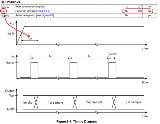
The Datasheet states that the time between points when the supply voltage reaches 1.65V and valid data on output pin is max. 100us.
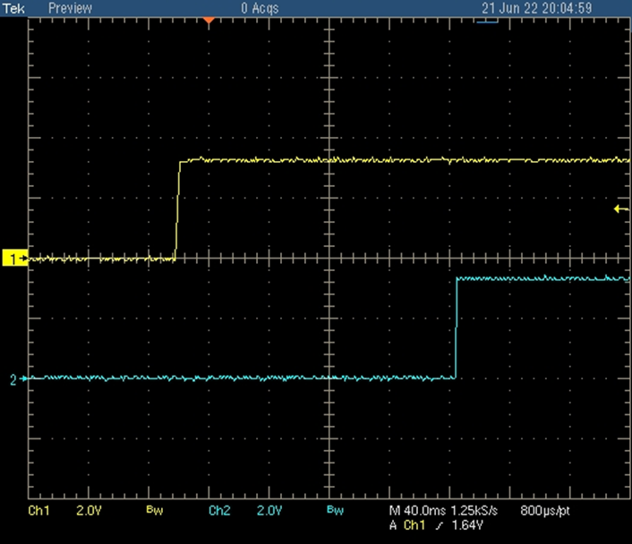
But in our application the valid output data appears only after the second sample (~47ms after start up).

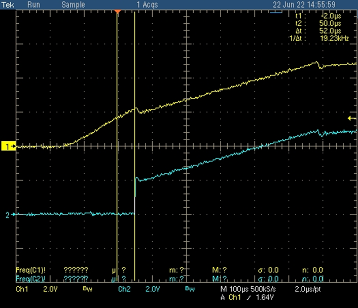
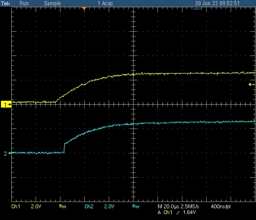
2 channel - VCC (+3.3V), 4 channel - Data Out
This problem was not present in the previous batch of devices
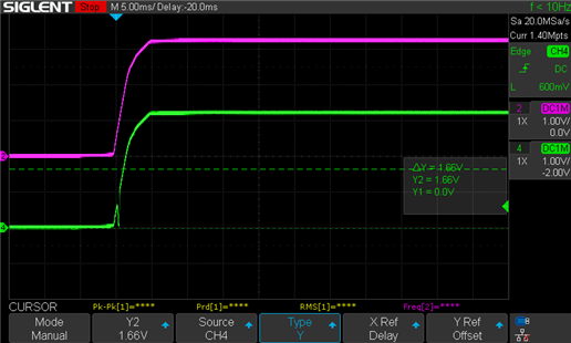
2 channel - VCC (+3.3V), 4 channel - Data Out
Is this normal IC behavior if the first sample is not valid?
For what reason may the behavior of the IC differ between batches?