This thread has been locked.

If you have a related question, please click the "Ask a related question" button in the top right corner. The newly created question will be automatically linked to this question.

IWR6843ISK: Advanced features

Part Number: IWR6843ISK
Other Parts Discussed in Thread: IWR6843,

Greetings!


I appreciate your prompt response and your willingness to support us.

The signal amplification module I mentioned earlier has the part number HMC-ABH209.

We assumed that it could be combined with the IWR6843 chip to get the transmit power up.

We saw a discussion of a similar case on some threads of your site (https://e2e.ti.com/support/sensors-group/sensors/f/sensors-forum/785133/iwr6843isk-do-i-really-get-40dbm-transmit-power-when-i-set-it-in-61-0-61-5ghz-range?keyMatch=IWR6843+40DBM) and assumed that the similar request could already be resolved positively.

That is why we turned to TI with a request for support.

In our understanding, the growth in transmit power will necessarily entail

1. Increasing in the volume of processed internal data, which will inevitably entail a greater need for the internal buffer size. And this, in turn, may require the use of external memory what looks dim now.

2. In addition we would like to clarify the possibility of increasing the ADC frequency up to 25 MHz. In this case, the internal memory sizes in the IWR6843 may not be enough and external memory will also be required.

3. The changes described above, in our understanding, will necessarily require modification of the firmware for the correct configuration of the overall system. And again, that's why we came to you.


Summary: the task that we now face is the following:

1. We want to increase the detection distance using TI chips (IWR6843+HMC-ABH209)

2. We would like to increase the ADC frequency up to 25MHz.


The query itself looks like this: does TI already have ready-made solutions with the indicated chips or others more suitable for our case?

If so, do you have designs and/or any descriptions that we could use for our goals?

  • Hello,

         Thank you for your query, What is the application you are targeting? There are regulatory restriction to use higher Tx output power based on frequency band and type of application targeted. 

    You could refer: TI mmWave Radar Device Regulatory Compliance Guide  https://www.ti.com/lit/an/spracp3c/spracp3c.pdf for more details.

    What is the distance that your are targeting with the external power amplifier? 

    For example using IWR6843 device with Three tree transmitter using simultaneously & Tx beam forming one could achieve upto 100 meters people detection capability without adding external power amplifier as shown in the below example.

    https://dev.ti.com/tirex/explore/node?a=1AslXXD__1.00.00.26&node=A__AFSylyb3s.Y0XGHAWn4NBg__radar_toolbox__1AslXXD__LATEST

    If you need further detection range, Above Power amplifier could be added to increase the link budget SNR. 

    ADC sampling rate is limited to max of 12.5MHz complex receiver chain and 25MHz real receiver chain, However FMCW slope could be adjusted such that max IF bandwidth could be limited to 10MHz, This would be traded-off with the range resolution to meet the max distance requirements.

    Thanks and regards,

    CHETHAN KUMAR Y.B.

  • Thanks for your reply.

    We have reviewed the recommendations in www.ti.com/.../spracp3c.pdf and verified that the authorized transmit power in the 60 GHz band is EIRP 20 dBm (100 mW), which will allow us to provide range over 100 m. TI only provide ~10 dBm.

    In your answer, we were interested in the idea (perhaps perceived by us incorrectly) that you propose to use 3 transmitting channels at the same time. Is it correct to assume that all three TX channels can work simultaneously, and not sequentially, forming a narrower beam and more radiation power?

    We expect to detect a fast moving vehicle over 200 km/h at a distance of more than 100 m.

    To solve this case, we need to emit a signal with a short pulse duration, a wide signal bandwidth, with increased power and receive a reflected signal using MIMO technology with digitization at a frequency of about 25 MHz.

    Can we apply standard firmware in this case from here dev.ti.com/.../node ?

    If we change the circuitry and put a chip in front of the antenna to amplify the power, the phase shifts in the receiving and transmitting channels of the antenna will change. Are there calculation and correction mechanisms in place for the correct operation of the built-in software for detecting the angle of arrival of the reflected wave?

    The task of detecting a fast moving vehicle over a long distance requires special signal processing that combines the results of TX and RX, and the task of refining the parameters of a fast moving vehicle over a long distance requires separate signal processing. This contradiction is realized by two different modes of operation of the radar, or by separate parallel signal processing. Do standard firmware have the necessary functionality to solve these two problems?

  • Zorin,

        Thanks for providing more details on the application.  Have you evaluated IWR6843ISK EVM? If not I would recommend to evaluate.

    Max IF frequency of the mmWave sensor could support is 10MHz, By adjusting the slope (Trade-off with range resolution) you could bring down the IF frequency within 10MHz to reach 100+ meter distance. 

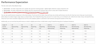
    You could refer to below expected performance numbers from the current demo code.

    https://dev.ti.com/tirex/explore/node?a=1AslXXD__1.00.00.26&node=A__AEeunV9ParnHsCl2FHemGw__radar_toolbox__1AslXXD__LATEST

    Regulation would allow higher Tx output power, but you don't need to put additional circuits to reach 100meters. You could consider

    Tx beam forming :  You could operate all the Three Tx together (Not one after the another) and this narrows the beam and increases detection capability. And you could use Tx phase shifter to align the beam at the desired location. Please note device has phase shifter only in the Tx path. And this will not be disturbed. You could refer below note for phase estimation 

    https://dev.ti.com/tirex/explore/node?a=1AslXXD__1.00.00.26&node=A__AE-Bpc-wQfi-OR.2V9TzCw__radar_toolbox__1AslXXD__LATEST

    You could use the Demo code, that would provide the angle of arrival as well for this configuration. Also for increasing the gain you could use Lens (which narrows the beam  but increases the SNR to reach further higher distance). You could use the mmWave sensing estimator to perform link budget analysis for the chirp configuration and trade-off with other Radar parameters.

    https://dev.ti.com/gallery/view/mmwave/mmWaveSensingEstimator/ver/2.2.2/

    FMCW radar provides both range estimation, velocity estimation and Angle estimation. Could you elaborate further on the "signal processing that combines the results of TX and RX, and the task of refining the parameters of a fast moving vehicle over a long distance requires separate signal processing"?

    Thanks and regards,

    CHETHAN KUMAR Y.B.