This thread has been locked.

If you have a related question, please click the "Ask a related question" button in the top right corner. The newly created question will be automatically linked to this question.

FDC1004: Channel flipping issue

Part Number: FDC1004
Other Parts Discussed in Thread: , FDC2214, LDC1314, LDC2114

Hi Experts,

We need your assistance to check our customer's inquiry below. I am posting this on behalf of the customer.

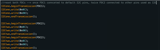
I am using your FDC1004 capacitance-to-digital converter to read values from capacitive sensors using either Arduino Pro Mini, an ESP32-wroom-32E or an ESP32-Mini-1. 
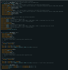
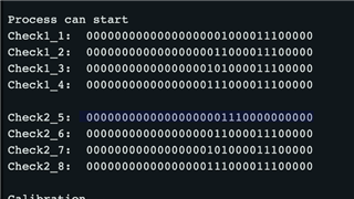
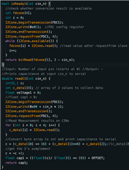
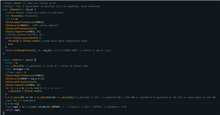
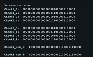
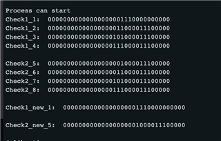
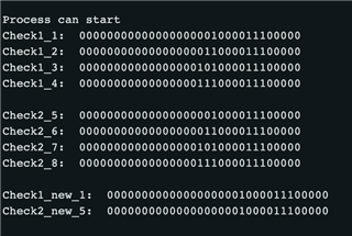
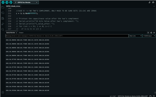
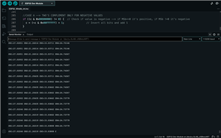
With all these chips I faced the same problem which is channel flipping during readout. In better words, the channels I read are flipped one position forward every other time I upload the code. So for example during the first reading, I would read on CH2 the value placed on channel1, on CH3 the one placed in channel2, on CH4 the one placed on channel3, and on CH1 the one placed on channel4. If I reset the chip (or upload again the code) they fix it till I don't upload the code again. This is why only every other time I upload the code or reset the chip I read the values in the correct order. I thought it might have been a problem with the Arduino, but I had the same issue with the ESP32.

I would like to be able to read the correct value of capacitance for ea.

Thank you in advance.

Best regards,

Jonathan

  • Hello Jonathan, 

    I have a few questions on this issue: 

    • Is the FDC1004 on your own board or the FDC1004EVM? 
      • Have you tested this with the FDC1004EVM and GUI? 
    • Is it possible for you to share your code related to the FDC1004 configuration and reading? 
      • In addition, what are the register settings for the FDC1004 for this measurement? 

    Thank you, 
    Justin Beigel

  • Hi Justin,

    Thank you for waiting for our update. Here is the customer's response below.

    - I am using the FDC1004 on my own board, I don't have the evaluation board
    - I haven't tested it with the FDC1004EVM and GUI, and I don't have the possibility to do so
    - I will send you the code where you can see also the register settings I used, I tried to follow the information on the datasheet to program the FDC configuration register (0x0C). You can see them on the code attached. Is there something missing for the registers settings?
    - I will attach also a simple schematic for the connection between the FDC and the arduino pro mini that i am using. The I2C pins are connected SDA to GPIO4 and SCL on GPIO5 on the arduino.

    FDC1004_ArduinoProMini.zipSchematic_ArduinoFDC1004.pdf

    - The schematic is pretty much analogous also for the tests I did with the ESP32 series, where I connected SDA to GPIO 21 and SCL to GPIO22. Also in this case the channels are flipped.

    Please let me know if you need additional information.

    Best regards,

    Jonathan

  • Hello Jonathan, 

    Your configuration for the FDC1004 looks good. I have a couple things that you could try to solve this issue: 

    • In your main loop, you could put a while loop before the first measurement to wait for the first data ready signal to appear. This would ensure that you don't have any misaligned data for the first data frame. 
    • You could try to view each channel's waveforms on an oscilloscope. Capturing the order the excitation occurs on each channel for the first round of measurements will help verify that the chip is measuring the channels in the correct order. 
    • After your register configuration, you can readback all the values for registers 0x08 through 0x0B to make sure the configurations were properly saved in the device registers. 

    Let me know if any of these solve the issue. If not, can you provide the oscilloscope capture so we can doublecheck the waveform? 

    Best Regards, 
    Justin Beigel

  • Hi Justin,

    Thank you for waiting. Here is our customer's response.


    I tried point one at the beginning of the loop but it didn’t solve the problem. I will attach to you what I did in the case of the ESP32, where I test two I2C connections to two FDC1004. What I did was add a while loop for each FDC at the beginning of the loop as you suggested. It didn’t work out.

    I tried also option number 3 with the registers check, implemented as you can see in the second screenshot. I hope I got it correctly.

    But I pretty much solved the issue by resetting the/both FDC1004 in the setup rising up a bit 15 (0x80) for register 0x0C.

    May I ask you also please if this formula to print out the capacitance value and convert it from byte array to int is correct?

    I get very different values for using the same code with Arduino Pro Mini or ESP32. In both cases, I enable the CAPDAC and use a programmable offset in the input of 21, but with Arduino, I start from a baseline value (no added capacitance) of ≈0.63, while with ESP of ≈30.63 on all channels. Is there a difference in conversion between the two chips?

    Is it something that deals with 2's complement? Or is my formula wrong?

    Thank you for your time.


    Best regards,

    Jonathan

  • Hello Jonathan, 

    The measurement range on this device is +-15pF. Getting a 30pF difference seems like it might be a matter of 2's compliment. To convert the data from the register value into capacitance, you can use the following formula: 

    It looks like all of your data is only 16 bits instead of 24. Each register in the FDC1004 is 16 bits long so to read the MSB_MEAS and LSB_MEAS, you will need to read 32 bits total: 

    Best Regards, 

    Justin Beigel

  • Hi Justin, 

    Here is the additional question from the customer.

    When I try to read back the values from the configuration registers, every few times with no recurrent pattern, I get the wrong values for the first channels on both FDC. This happens in both the case of the Arduino and of the ESP32, for example, it happens every few times while unplugging and plugging back in the USB into my computer. You can see an example of a wrong register readout in the pic attached for the case of the ESP. Do you know why this happens? It gets fixed by resetting the Arduino.
    Additionally, I discovered that when I use two FDCs and so two I2C connections with the ESP32, I have to reset once the first FDC is connected to the default I2D pins and twice the second FDC is connected to other pins. Do you know why? I attach here also the code used to reset the FDCs.

    Here attached there is also the code I used to read out the data and do the final conversion from binary array to pF capacitance value. Is this the correct way to save the 24-bit data and do the 2's complement conversion? I am not sure it is, with respect to the values I am reading out.

    Thank you so much for your usual support.

    Best regards,

    Jonathan

  • Hello Jonathan, 

    I have a couple clarification questions for these issues: 

    • Can you share an oscilloscope capture of the I2C transactions when they are having the incorrect data issues? 
    • When you say you have two I2C connections to two FDCs, do you have separate I2C connections on the ESP32? 

    Best Regards, 

    Justin Beigel

  • Hi Justin,

    Here is the customer's answer below.

    - I will send you the oscilloscope captures as soon as possible
    - The two FDC2 are connected through separate I2C connections to the ESP32. The First FDC is connected to the default pins 21-22 (SDA-SCL); the second one is connected to pins 33-32 (SDA-SCL)

    Best regards,

    Jonathan

  • Hello Jonathan, 

    I will wait for the scope captures but I also have one other question. 

    If you read the first register twice, does the incorrect value go away or is it present both times? 

    Best Regards, 

    Justin Beigel

  • Hi Justin,

    here is the customer's response to your latest question.


    Yes If I read it out twice the problem persists. I will attach to you two screenshots of this trial. In one the values are correct, in the other (obtained after I unplugged and plugged back in the USB into my computer) the registers are not correct.

    Moreover, can I ask you again about the formula for reading out the data and converting it to capacitance in pF? Is it correct if I read 3 bytes or 4 bytes (I will attach again the picture)?

    Thank you for your usual support.

    Best regards,

    Jonathan

  • Hello Jonathan, 

    I am wondering if the incorrect register value is just an I2C misalignment. When you reset the device, it looks like you are just sending an 8 bit value to the first half of the config register. If you alter the reset command to send a full 16bit value (0x8000), do you still get this issue occurring occasionally? 

    For the reading of the data, it is best to read all 32 bits of the MSB and LSB registers then discard the 8 reserved bits. Then, once you combine the MSB and LSB bits, you can use the formula shared above. 

    Best Regards, 

    Justin Beigel

  • Hi Justin,

    Here is our customer concern and response. 

    I tried what you suggested, resetting all 16 bits with 0x8000, but in this way, the problem of channel flipping persists.

    To use the formula you suggested for obtaining the capacitance value, can I replicate it in C as follows in the picture? Or do I have to do the 2's complement differently?

    Best regards,

    Jonathan

  • Hello Jonathan, 

    Implementing your 2's complement the way it is in your code is fine. 

    To clarify on your issue, does the incorrect register value still persist or just the channel flipping at this point? 

    Best Regards, 

    Justin Beigel

  • Hi Justin, 

    Here is the customer's response below.


    Yes, the register is set up correctly if I reset both FDCs once using 0x8000. But the flipping persists, channels now are flipped without a regular pattern (for example one reset yes, another two no, another two yes, another one no, etc... with no regularity), and also the pattern is not the same for FDC1 and FDC2.

    I attach here what I see from the readback of the register setup and the function I use to reset the FDCs.

    Thank you for checking.

    Best regards,

    Jonathan

  • Jonathan,

    Justin is out of office, but I have a few questions.

    How are you applying a known input capacitance to the channels so you can tell the readings are flipped?

    What do you observe if you use only a single channel with a stable value at the input?

    Regards,
    John

  • Hi John,

    Here is our customer's response.

    I am using constant capacitors of either 10pF or 4.7pF to test the readout. I tried both the case of one single channel with stable input and all channels with stable input.

    Best regards,

    Jonathan

  • Jonathan,

    Thanks Jonathan.

    Justin said the code they have shown looked good, which leaves us with an unclear path on how to move forward.

    Let's re-start with some experiments.

    1. If they haven't done so already, please have them connect different capacitance values to the input pins.
      For example, connect 0pF to input CIN1, 4.7pF to CIN2, 10pF to CIN3 and 2x10pF to CIN4 inputs.
    2. Set CAPDAC equal to zero for all of the measurements that follow.
    3. Have them take moderately long single-channel measurements of each individual channel.
      For each channel measurement what values of capacitance do they see in terms of the average and standard deviation?
      Do they reflect the values of the capacitors connected to the input pins? 
    4. If the answer to (3) is "yes", the next step would be to do pair-wise two-channel measurements of CIN1 and CIN2, CIN1 and CIN3, and CIN1 and CIN4, and note the results (CIN4 readings should saturate).
      For each channel measurement what values of capacitance do they see in terms of the average and standard deviation?
      Do they see stable, expected values, or do they see wrong values and/or channel-flipping as described earlier in the thread?
    5. If they see the expected, stable values in step (4) for two-channel measurements, then move on to three-channel measurements {CIN1, CIN2,CIN3} and {CIN2,CIN3,CIN4} and note the results.
      For each channel measurement what values of capacitance do they see in terms of the average and standard deviation?
      Do they see stable, expected values, or do they see wrong values and/or channel-flipping as described earlier in the thread?
    6. If steps 2,3 & 4 look okay, move on to four-channel measurements.
      For each channel measurement what values of capacitance do they see in terms of the average and standard deviation?
      Do they see stable, expected values, or do they see wrong values and/or channel-flipping as described earlier in the thread?

    I know this will be tedious.
    At this point we still don't know if this is an issue related to the analog or digital part of the circuit, or if this is a problem with the customer's firmware.

    So please ask them to share the detailed results of each experiment (3-6), including the average and standard deviations of the outputs in terms of capacitance  from the FDC1004 as well as their general observations and comments. 

    Last question: Are they using exactly the same code for the different processors?

    Regards,
    John

  • Hi John,

    Thank you for waiting. Here is the customer's response below.

    To better understand what I am talking about, I will attach here both the code I am using to read out the data and convert to capacitance values (“ ESP_acquisition_2FDCs”) and the one I am using to check and read back the registers set-up (“Readout_registers_esp32_2fdcs”). So your colleague can help me better and not struggle.
    To better answer the questions of Mr. Miller, I would like to ask you a specification. “What do you mean with “pair-wise two-channel measurements”? Is it differential measurement or simply channels connected to constant capacitances and readout simultaneously? Please note that to me it’s a firmware issue, not related to the analog or digital part of the circuit.

    To me it's a readout problem, so my questions would be:
    - Am I reading out the 32 bits correctly and then considering only 24 of them for the conversion?
    - Is the 2's complement implemented correctly?
    - Are the registers correctly setup? (to me it seems fine)

    Here is a short answer, but still I have a couple of questions regarding what they ask on point 4:
    1. I have done this already using 10pF and 4.7pF on alternative channels, I will do this with the capacitances you suggested. I am using à FDC1: 10pF on CH1 and CH3, 4.7pF on CH2 and CH4, FDC2: 4.7pF on CH1 and CH3, 10pF on CH2 and CH4.

    3. If you mean to keep the capacitance plugged in for a long time and see the readout value…. On average the values in input are reflected (subtracted from the baseline (probably parasitic capacitance): e.g. baseline= -3.1pF, value -13.7 pF). But values don’t reflect when there is overflow or the baseline is too close to the edges of the capacitive range, as it goes out of range. If I don’t apply the reset function it’s the same.

    4. I am not sure I understand what you ask with “pair-wise two-channel measurements” —> my answer would be pretty much the same as for answer 3, I tried many different combinations of channels, considering single measurements and not differential ones. The flipping is not due to this combo. I see stable expected values, just a bit higher as multiple capacitances are placed in parallel. Same also if I don’t reset the fdc. I don’t see saturation in CH4 in any of the 2 cases. What do you mean with that?
    5. Same as for question 4, I see stable expected value as expected. Same also if I don’t reset the fdc.
    6. Same also here. Same also if I don’t reset the fdc, the channels stay stable. No weird flipping or saturation, unless I physically reset the chip (in that case there is flipping, if I don’t use the reset function for the fdc).
    7. I am just using the same code, just with an extra library for ESP (#include <dummy.h>), and I am using the TwoWire expression of the Wire library for 2 fdc

    I have one more question. To select the 24 bits for the final conversion and to do the 2's complement, is it well also this implementation?
    if ((c & 0x800000) ! = 0) { // Check if value is negative --> 2's complement
    c = ~c + 1; // Invert all bits and add 1
    }

    or just simply c= ~c +1?
    or
    if ((c & 0x800000) == 0) { // Check if value is positive --> 2's complement
    c = ~c + 1; // Invert all bits and add 1
    }

    As the values I read change very much with respect to the bits selected

    2FDCs_esp32.zip

    Best regards,

    Jonathan

  • Jonathan,

    Thank you for the additional details. I will read through it and update the thread tomorrow.

    Regards,
    John

  • Jonathan,

    Sorry I wasn't clear about the proposed pair-wise measurement strategy.

    What I meant in item (4) of my last reply was to set up sequential two-channel measurements, first with CIN1 and CIN2, then with CIN1 and CIN3, and lastly with CIN1 and CIN4., and look at the average and standard deviation of the readings, and also look for channel-flipping.

    If that looks okay then move onto three-channel measurements as described in item (5) of my last reply, and so on.

    Regards,
    John

  • Hi John,

    Thank you for waiting,

    Here is the customer's feedback.

    Considering a capdac=0, I obtained the expect stable values (a bit of noise in nF is always present for sure) all on top of a baseline capacitance of ≈3.5pF for all 4 channels. In all cases, I obtained ≈4.7pF for ch2, ≈10pF for ch3, and saturation for ch4 (≈16pf fixed saturated, placing 20pF as constant capacitance).

    If I do not reset the FDC I still have channel flipping every other upload or every other tiem I reset the chip (channels are printed out one position forward). If I reset addressing (0x8000) I still have channel flipping.
    If I reset addressing (0x80) I do NOT have flipping, in this case the used code to not have flipping is:
    Wire.beginTransmission(SLAVE);
    Wire.write(0x0C);
    Wire.write(0x80);
    Wire.endTransmission();

    Please note, when I mean resetting the fdc by code is different than physically resetting the chip using the button on the dev board.

    Please note, that I am using the following forumula for the two's complement conversion:
    if ((c & 0x800000) ! = 0) { // Check if value is negative --> 2's complement
    c = ~c + 1; // Invert all bits and add 1
    }

    Note also that to me it's a readout problem, so my questions would be:
    - Am I reading out the 32 bits correctly and then considering only 24 of them for the conversion?
    - Is the 2's complement implemented correctly?
    - Are the registers correctly setup? (to me it seems fine)

    To be more precise, if I use two FDCs. The second one has to be reset twice to avoid flipping. Always considering (0x80). Do you know why?

    doing some more tests I came up to the conclusion that the point is how I configure the lowerbyte of the configuration register for the cases with capdac≠0.
    I have always used the following code, which seems to be wrong to me:
    int capdac = round(OFFSET/3.125);
    for (int i = 0; i < NUM_SENSORS; i++) {
    int register_value = 0x1000 + (capdac << 5);
    Wire.beginTransmission(SLAVE);
    Wire.write(0x08 + i); //address the measurement config register for the 4 channels
    Wire.write(highByte(register_value) + 32 * i);
    Wire.write(lowByte(register_value));
    Wire.endTransmission();
    }

    If I consider capdac=0, I used the following:
    Wire.beginTransmission(SLAVE);
    Wire.write(0x08 + i);
    Wire.write(0x10 + 32 * i);
    Wire.write(0x00);

    Apparently the error is in the setting for capdac≠0

    Best regards,

    Jonathan

  • Hello Jonathan, 

    Thanks for the additional information. I have a couple comments in response to their feedback: 

    Note also that to me it's a readout problem, so my questions would be:
    - Am I reading out the 32 bits correctly and then considering only 24 of them for the conversion?
    - Is the 2's complement implemented correctly?
    - Are the registers correctly setup? (to me it seems fine)

    The register read, 2's complement, and register setup seem okay. I don't see any issues with any of these that could be causing these problem you are having. 

    To be more precise, if I use two FDCs. The second one has to be reset twice to avoid flipping. Always considering (0x80). Do you know why?

    I am not sure why they are having to reset the second one twice. Is it possible to connect an oscilloscope to the I2C channels and check the transaction around the reset? 

    Apparently the error is in the setting for capdac≠0

    Have you tried changing the 'highByte(register_value)' command to a fixed register value offset for the capdac in the firmware? 

    Best Regards, 

    Justin Beigel

  • Hi Justin, 

    Appreciate it. Here is our customer's feedback below.

    I have fixed the register configuration (high and low bytes now should be correct). The reading might still be a problem, and also the two's complement conversion. With this code, if i give in input a constant capacitance to the channels I am not reading the values expected for capdac values different than 0. Could you please help me with the readout and conversion? The last 8bits of my 32bits data should be all 0s, but in my case they are all 1s.

    See attached zip file.

    ESP32_OneFDC_4channels.zip

    Best regards,

    Jonathan

  • Hello Jonathan, 

    Thanks for the information. I have a few follow up questions:

    Is the capacitance reading incorrect for all constant cap measurements or just the ones that are expected to be negative with your current CAPDAC setting (all but the 20pF cap based on the code shared)? 

    How far off are the measurements from the expected value? Are the values constant or noisy? 

    Best Regards, 

    Justin Beigel

  • Hi Justin,

    The capacitance is not read correctly for most of channels. Sometimes it gives a smaller value and other times it doesn't even change with respect to the baseline value. All values are very noisy (terms of 0.05/0.1 pF).

    I have few of questions :
    1. If I define an "int" value, considering that "signed integer type use 2's complement for negative values", does it mean that the 2's complement is already done and I don't have to do it by code?
    2. so do I have to do always the 2's complement, or only for negative values? or only for positive? or never?
    3. Using ESP32, is it correct to define these variables as "int" and not as "uint"?: int c_data[4] = {0}; / int c = 0; / int msb = 0; ... Apparently the results change a lot in the two cases, in terms of binary outputs (Incorrect for uint).

    I will attach here a newer version of the sketch in which I am using "int variables", I will send you results w/ and w/o 2's complement.

    Please note that in the two screenshots attached:
    I have placed 0pF on CH1, 4.7pF on CH2, 10pF on CH3, 20pF on CH4. WIth initial offset of 15pF.

    For an initial set up at "OFFSET= 15" as in the case of the screenshots and code provided, the baseline value I read on all four channels is ≈35 in the case without two's complement, and ≈26.9/27.4 in case of using two's complement for the same initial offset.

    If I place the initial offset=0, so no capdac, the baseline is ≈3.5/3.0

    Thank you once again for your usual support.
    Best regards,
    Jonathan
  • Hello Jonathan, 

    1. If I define an "int" value, considering that "signed integer type use 2's complement for negative values", does it mean that the 2's complement is already done and I don't have to do it by code?

    If the variable is already a signed integer, you should not need to perform a 2's complement conversion on it. Though if the integer is 32 bit while the data is only 24 bits, the negative portion may not be properly detected. You could mask the 8MSBs if you check for a negative 24 bit number to ensure the negative number is found correctly. 

    3. Using ESP32, is it correct to define these variables as "int" and not as "uint"?: int c_data[4] = {0}; / int c = 0; / int msb = 0; ... Apparently the results change a lot in the two cases, in terms of binary outputs (Incorrect for uint).

    I am not very familiar with the ESP32 but you can double check if the data is being changed by the integer format by just printing out the bits from the register read and comparing that to after it is assigned to the different integer types. 

    It looks like there is a line for the MSB and LSB data registers to print to the terminal in the provided code. Does the output to this align with expectations from the device? 

    Best Regards, 

    Justin Beigel

  • Hi Justin,

    Here is the customer's response.

    1. given what was stated by your colleague, and defining:
    c = (msb << 8) + (lsb >> 8);
    c = (c & 0x00FFFFFF); --> mask to consider only bits [23:0]

    In which case then I have to perform the 2's complement?
    a) in case of ONLY positive c values (as in screenshot)
    b) in case of ONLY negative c values
    c) NEVER
    d) ALWAYS
    Is my mask correct? Plus see the screenshot attached for this part of sketch.

    2. The output of MSB and LSB in binary form aligns with the c_data elements, but not with my expected results. I have positive 'c' values for an initial OFFSET=0, 1 and sometimes for 2 and 3. Then all values are negative.
    Moving from positive values (0,1 as initial offset) to negative values, gives a huge gap on the baseline readout ( the one I get as result if I do not insert any physical capacitance) of around 20 pF. Are you able to tell me why, please? I will soon send you an excel file with examples.

    3. Do you have any examples of sketched dealing with cases similar to mine? Like reading out capacitances value on all four channels of the FDC1004 using an ESP32 as microcontroller or also with Arduino? Like any case related to capacitance readout and application of the final conversion formula including negative/positive values differences and the two's complement conversion. I couldn't find any online, but if you could help me with sending some of them, they would be really useful and appreciated, thanks.

    4. In the conversion formula in the part related to ( + Coffset), should I add the initial OFFSET defined as constant int variable at the beginning of the code (e.g. int OFFSET= 15;) or should I consider the value obtained starting from capdac. Considering " int capdac = round(OFFSET / 3.125); "., the new Coffset would be " int Coffset= round( capdac *3.125);". Which one is correct, adding OFFSET or Coffset?

    5. If I am understanding correctly, increasing the initial OFFSET (hence increasing the capdac value) increases the capacitance values I can read out. So for example:
    - OFFSET=10 --> allows me to read capacitances from (-5 to 25 pF)
    - OFFSET = 15--> allows me to read capacitances from (0 to 30 pF)
    - OFFSET = 30--> allows me to read capacitances from (15 to 45 pF)
    - up till a Coffset of 96.875pF with a capdac value of 11111=31.
    Is this correct? So in this case my range of readable values should shift forward of a number of positions proportional to the increase in the OFFSET, but this doesn't happen.

    6. Which type of variable should my final cap value be? Is it ok to define it in this way with the following conversion formula? Changing it by a minimum amount changes everything:
    double cap = (c / 524288.0) + OFFSET;

    I will send you the Excel with the examples soon, I am not able to read out any correct value.

    Best regards,

    Jonathan

  • Hello Jonathan,

    1. The mask is good to make sure you just have the proper number of bits, but if it is assigning into a 32 bit variable it could cause a negative number to not register as one. For example, if you have -657 (which can be represented by 12 bits) as your number in 16 bits (for ease of typing out), it would be: 1111 1101 0110 1111. If you mask that to be a 12 bit number, but your variable is still 16 bits, it would become 0000 1101 0110 1111. This would cause it to still be a negative 12 bit number, but my 16 bit variable would no longer recognize it as a negative number automatically.
      1. I recommend printing out the bitwise or hex code of your number before and after the mask to understand if this is happening in your code. From there, you can determine if you need to manually perform the 2's complement. 
    2. I am not sure why this is happening in your setup. I will look at the excel files when you send them over and hopefully will understand better then. 
    3. We do not have any examples for the ESP32 or using Arduino for this device. All of our development we have to share has been around the FDC1004EVM and our GUI. 
    4. Coffset would be more accurate. You will want the value that the device is actually using to offset the measurement rather than the targeted value. 
    5. Yes this understanding is correct. 

    Let me know when you have the excel ready and if any other questions pop up between now and then. 

    Best Regards, 

    Justin Beigel

  • Hi Justin,

    Here is our customer's update.

    Sorry to haven't replayed it yet, I am still working on the Excel file. I will send it to you by the end of the week. I had other work priorities that overlapped.

    In the meantime, may I ask you please if it's possible to use other T.I. components in place of the FDC1004?
    Specifically, can I use the FDC2214 for the same purpose? or is it only for proximity sensors with a too-big range?

    What about using an inductance-to-digital converter such as LDC2114 or LDC1314 to read back capacitance from inductance in a resonance-based approach? is it also possible? do you have examples in this last case?

    Best regards,

    Jonathan

  • Hello Jonathan, 

    We don't recommend the FDC2214 for most designs due to issues with EMI. The built in shield driver of the FDC1004 helps mitigate these issues. 

    With the LDC products, any capacitive effect on the sensor will be very small to any moving metal in the sensing area. So if you have any metals near your sensor, the capacitive impact can be difficult to consistently measure. We would not recommend using them over the FDC1004 for capacitive sensing. 

    Let me know when the excel file is ready and hopefully we can fix the issue you are having with the FDC1004. 

    Best Regards, 

    Justin Beigel

  • Hi Justin,

    Thank you for your support once again.

    Here is the customer's update:

    Here attached you will find a folder with the sketch I am using for my tests, the excel file for different capacitance value I obtained in the different channels for different initial OFFSET. I added a 10pF capacitance to channel 1 and 2 for simplicity, leaving the others free. I also added a couple of screenshots expressing some relevant parts of the sketch and problems I'm facing:
    - "2comp_passage"-> formula used for the two's complement. I check if bit [31] of the c-value is 1 or 0. If 1 (neg) I will only perform the mask to save 24 bits. If it's 0 (pos) I will do both mask and two's complement. My question now would be if I need to add "1" in position 23 if I found the value to be negative (1 in position 31).
    - "bit_problem/example" -> printing out the binary, I realised that in some passages (randomly) the msb and lsb (and so the c-value) get composed wrongly with the shifting wrt the 4 8-bit elements read from the FDC.

    ESP32_FDC1004.zip

    Best regards,

    Jonathan

  • Hello Jonathan, 

    A few questions about the spreadsheet: 

    • Is the baseline value after the 2's complement section of the code? 
    • Baseline is with nothing connected to the sensor pin correct? 
    • Is it possible to add the corresponding binary values of the register reads before any processing to the excel sheet?
      • If you are still working on fixing the combining of your C_data array into MSB/LSB, you can just add the C_data values in 4 different collumns

    Best Regards, 

    Justin Beigel

  • Hi Justin,

    Here is the customer's response below.

    - the baseline value is what I read at the very end, already after the 2's complement and after the conversion formula to bring the value to pF.
    - the baseline is what I get if NO sensor pin is connected, it changes for the different initial offset but not in a linear way.
    - I will add the binary values to the excel sheet and give it back to you.

    Here a couple of questions from my side, pelase:
    - when exactly do I have to do the 2's complement? only in case of positive values?
    - What do you mean that for MSB/LSB i can just add the C_data values in 4 different columns? DO you mean something like this: c = (c_data[0] << 16) + (c_data[1] << 8) + c_data[2]; ? or even different?

    More precisely, the issue with bites might be either related to the type of variables used and the shifting, cause also as you can see in the previous screenshot. The msb/lsb and c value before two's complement do not correspond to the 4 bytes read out and then shifted.

    Please note that all the capacitance values in the excel file are AFTER the conversion to pF using the formula:
    double cap = (c / 524288.0) + Coffset;

    Thank you.

    Best regards,

    Jonathan

  • Jonathan,

    Just so you know, Justin is unavailable for a few days.

    I will read thru the thread and reply by COB on Monday, .

    John

  • Jonathan,

    I don't have any useful suggestions or answers to your questions.
    Justin should be available tomorrow to give some feedback.

    John

  • Hello Jonathan, 

    With the swtich to "int32_t" variable type, I am not sure you need to be doing the 2's complement at all. It is hard to say for sure when the combining of the MSB and LSB registers is incorrect as you showed in the bit problem image. 

    What do you mean that for MSB/LSB i can just add the C_data values in 4 different columns? DO you mean something like this: c = (c_data[0] << 16) + (c_data[1] << 8) + c_data[2]; ? or even different?

    I am suggesting that you create 4 new columns in the excel sheet for c_data[n] instead of combining them or processing them first. 

    Best Regards, 

    Justin Beigel

  • Hi Justin, 

    Hoping you can still support this thread. The customer responds back after a month.

    I am using two FDC1004 to read data from a total of 5 to 8 textile sensors and I am running into crosstalk effects when reading from both FDCs. I am using an ESP32-mini-1. This happens only with physical textile sensors and not with constant capacitances. If I read only the 4 channels from the f1st FDC (connected to default I2C pins 21-22), I don't have problems. But as soon as I add also the channels from the 2nd FDC (pins 33-32) I start having oscillating noise in all the channels for both FDCs. Could you please help me with this? Should I shield physically the sensors or do something in my firmware? Is there a way to turn on-off one alternatively the FDCs when I am not reading them, so that they are not on at the same time?

    Hoping for your kind response.

    -Mark

  • Hello Mark, 

    With the FDC1004, you can enable the device to only take one measurement before going back to standby. You can do this by setting the REPEAT bit of the FDC Configuration register to 0: 

    This way, you can initiate measurements on one FDC at a time to prevent the crosstalk from occurring. 

    Best Regards, 

    Justin Beigel