What is the frequency generated by the Ground Neutral driving pin NG_OUT?
This thread has been locked.
If you have a related question, please click the "Ask a related question" button in the top right corner. The newly created question will be automatically linked to this question.
Hello Ruy,
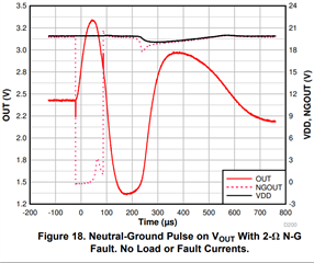
The NGOUT pin is a PWM signal. It is high (at 20 V) and is switched to GND level every half line cycle. The low time (time NGOUT is at GND) is approximately 100µs before it is switched back up to 20-V rail. The NGOUT pin follows this pattern indefinitely unless the device fails a self test or detects a fault.
Figure 18 in the datasheet shows the NGOUT pin and the resulting ripple sensed by the 1000-turn current transformer + AFE3010 internal amplifier when there is 2-Ω neutral to ground fault present. This is what the ripple amplitude should look like in order to achieve robust Neutral-to-ground detection over UL 943 testing standards.
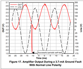
When there is no neutral-to-ground fault present, you can see small current ripples on the OUT signal every half line cycle. These ripples are far too small to trigger a neutral-to-ground fault within the digital core.
Hope this helps.
Best,
Peter
Hello Ruy,
Correct. The oscillation directly measured by AFE3010 internal amplifier is the result there being a neutral-to-ground fail present. Current is injected into the 200 turn coil and this forces a common current on the line. Any neutral to ground leakage will mean there is a differential oscillating current left.
Sincerely,
Peter