


Questions: Where can I download the LDC3114 Pspice model, and what type of simulations does it support?
How should the model be configured, and how does it work with the time-varying sensor model?
The Pspice for TI model and test bench for the LDC3114 is now available for download from the Design Tools & Simulation section of the LDC3114 product folder.
The model is intended for time-domain transient simulations of the LDC3114 in raw data model.
Note that the model's netlist is encrypted for use in Pspice. It will work in the free version of Pspice for TI, and in the commercial version of Cadence Pspice.
The model will not be usable in other simulators.
No button-mode features are supported by the model.
Why?
The model’s sinusoidal sensor waveform (5MHz-30MHz) forces the Spice simulator into small time steps (~1nsec - ~10nsec) to minimize errors.
Button mode uses internal algorithms – like baseline tracking – that are meant to track environmental fluctuations (like temp) that work on much longer time scales than the sensor’s oscillator signal (e.g. minutes, hours).
Using Spice to simulate a circuit with such divergent time scales – nanoseconds versus hours – is not realistic.
The Pspice test bench also includes a time-dependent model of an inductive sensor, which can be easily modified to suit the needs of the design.
The LDC3114 model two device parameters, LCDIV and SENCYC, which control the width of the device sampling window. For more information on how these parameters affect the device behavior, please see the LDC3114 data sheet.
You should see the schematic below upon opening the test bench for the first time:
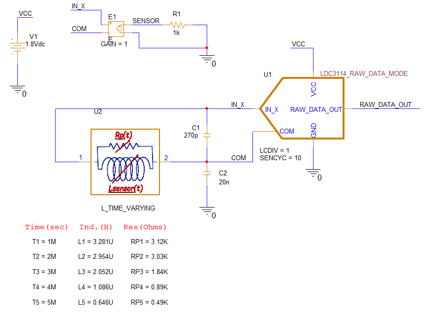
Time-varying sensor model - Calculating new values and entering them in the Pspice model
Consider the LDC3114 inductive sensor is intended to detect a moving, conductive target. As a conductive target moves closer to the inductive sensor, the sensor inductance (L) and equivalent parallel resistance (Rp) will decrease. As a target moves away from a sensor, L & Rp will increase.
This can be simulated by computing a series of L & Rp values using the Inductive Sensing Design Calculator Tool for different Target Distances, and entering the L & Rp values in the Pspice time-varying sensor model, and then running a transient sim in Pspice for TI
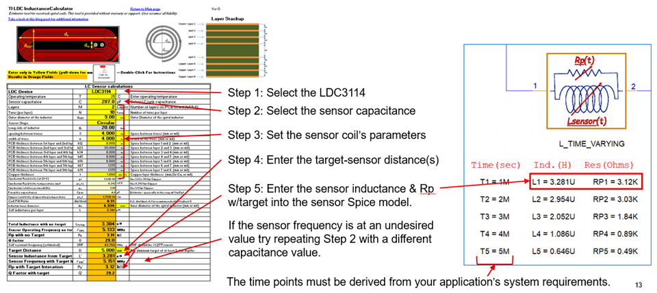
The sensor L's and Rp's can be easily calculated with the Excel-based Inductive Sensing Design Calculator Tool.
Schematic text (not shown here) describes how the default sensor L & Rp values were calculated using the calculator tool.
The following graphic outlines the steps for computing new inductor and Rp values, the then entering them in the sensor Pspice model on the schematic.
The left side of the graphic shows the landing page of the calculator tool. The middle of the graphic shows the steps for entering input parameters and noting the resulting output values for inductance and Rp for a given target distance. The right side illustrates how to enter the new inductance and Rp values in the Pspice for TI sensor model.
You can change any of the parameters of the time-varying inductor Pspice model by double-clicking on the value and entering the desired value in the pop-up.
How will the models of the time-varying inductor and the LDC3114 affect the choices of the sim conditions, and the results?
First, consider the LDC3114 model's time-related sampling parameters LCDIV and SENCYC.
The LDC3114 model has two parameters: LCDIV, SENCYC that control the sampling interval of the sensor waveform via the equation:
W=128∙(1+SENCYC)∙2LCDIV
Where: LCDIV = 1..7 (default 3)
SENCYC = 0..31 (default 4)
The time duration of the sampling interval:
tSAMPLE = W∕fSENSOR
where the LDC3114 will output a data word at the end of each sampling interval.
Example
Assume a sensor frequency fSENSOR = 10MHz, default LCDIV (= 3) and SENCYC (= 4).
The LDC3114 sampling interval will be W = 5120, and the sampling time will be tSAMPLE = W/fSENSOR = 5120/10MHz = 0.512msec.
So, for the entire sampling window – and subsequent LDC3114 data conversion – to finish successfully, the Spice sim time (TSTOP) must be > 0.512msec to capture the one sampling window.
Simulating multiple sampling windows will require multiples of the 0.512msec for Pspice transient simulation time: TSTOP ≥ N*0.512msec.
For our 10MHz sensor and the max values of LCDIV & SENCYC (7&31), the sampling window would be 52.43msec, which could result in a very l-o-n-g simulation time.
Summary: to ensure the most efficient, accurate sims, please pick the smallest possible values for LCDIV and SENCYC that will meet your application’s requirements.
Make Spice TSTOP > M∙tSAMPLE where M is the desired number of LDC sampling widows in the sim.
Next, consider the time-varying inductor model.
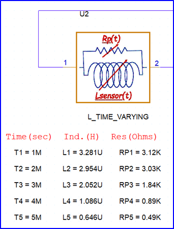
The sensor model uses two Spice TABLE structures - {TN,LN,} and {TN,RpN} – for the coil’s inductance and parallel resistance.
What are the implications?
The sensor model gives the following behavior with respect to the Pspice simulator’s transient TIME parameter:
For Spice sim TIME < T1, Lsensor = L1 and Rp = RP1.
For Spice sim TIME > T5, Lsensor = L5 and Rp = RP5.
For Spice sim TN > TIME > TN+1 Lsensor & Rp values are a linear interpolation between those values at TN and TN+1.
Example
Assume the LDC parameters from the previous slide (W = 5120, tSAMPLE = 0.512msec) will be used in a sim that includes the sensor figure shown just above.
The LDC3114 model will perform conversions in nonoverlapping TIME windows with widths of 0.512msec.
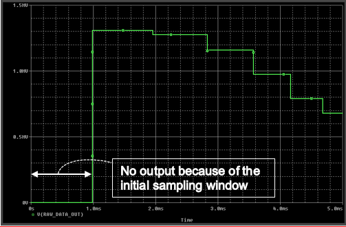
The only time periods where the sensor’s inductance will be constant over the LDC3114 sampling window will be TIME < 1msec and TIME > 5msec.
As the sim TIME goes from 1msec to 5msec, the sensor L & Rp will vary over the LDC3114 sampling windows, which impact the LDC3114 raw data output after conversion of the sampling window data. Application requirements will determine if this is a realistic sim.
How will the models' parameters affect the sim results?
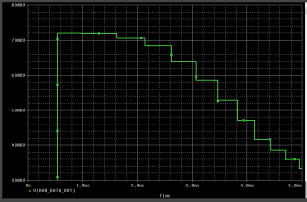
The plots below serve as an example of the dependence of the sim results on the models’ parameters.
The top plot uses the test bench parameter values, LCDIV = 1, SENCYC = 10.
The second plot uses the device's default values for LCDIV & SENCYC (= 3 & 4).
While the sample window (W) stays constant during each sim, the sample time (tSAMPLE) decreases during each dim because the of the time-varying sensor parameters (L & Rp) cause fSENSE to increase.
SENCYC = 10, LCDIV = 1 , W = 2816
SNCYC, LCDIV = 3, W = 5120
Thank you for your interest.
If you have any questions or feedback about this model, please submit them to this E2E forum.m
