This thread has been locked.

If you have a related question, please click the "Ask a related question" button in the top right corner. The newly created question will be automatically linked to this question.

TMAG5273: TMAG5273

Part Number: TMAG5273

Hello,

I am using the TMAG5273 for testing in order to detect the magnet's location.

I have both the A1 and A2 version as i am testing which one is more suitable in my application.

I am using ESP32 as a uC to get the I2C values

I am using these parameters in the register mentioned (continuous mode - and X,Y,Z channels enabled - magnetic range for all axis 80mT)

I also followed the datasheet to get the value of B.

but the results seems not correct, even when there's no magnet at all the value fluctuate between 0 and 159. the fluctuation is random so there's no pattern.

I am not quite sure what cause this problem and how i can fix it?

The problem remain even if i change the magnetic range to 40mT or change the A2 version.

The IC detect the magnet when it's near the IC but when the magnet doesn't exist it start to fluctuate (sometimes it stay in 0 for few seconds and sometimes in 159 for few seconds). 

You can check the image attached.

Is there anyone who tested the device could provide me any support about the reason?

Looking forward to your support.

Thanks.


  • Fedi,

    thanks for reaching out on E2E.  Can you please send your register configuration settings?

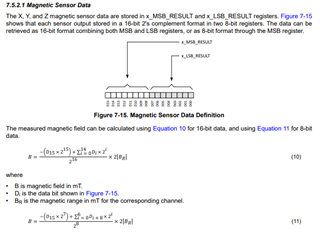
    Also, the output format of the sensor data will be in 2s compliment.  So when sitting idle you should see the output switch between positive and negative values.  Are you reading both the MSB and LSB of the output?  There should be two 8 bit reads which are used in this calculation:

    thanks,

    Scott

  • Hello,

    Thank you for your reply.

    I am using these configuration for the register

    I2CWrite(DEVICE_CONFIG_2, 0x02); (continuous mode)
    I2CWrite(DEVICE_CONFIG_1, 0x02); (read 8bit sensor MSB data)
    I2CWrite(SENSOR_CONFIG_1, 0x70); (enable X,Y,Z channels)

    I am also usng the (11) equation to measure B as i am getting only the MSB values depending on the datasheet.

    Do you see something wrong with this?

    Looking forward to your reply,

  • Fedi,

    I would anticipate seeing the device alternate between codes on either side of 0.  This is a result of input referred noise and can be reduced by increasing the averaging.  The value of 159 does not make sense to me though. I want to be sure I understand what you are seeing.  Is 159 the decimal conversion of the binary value (1001 1111) or is it the result of equation 11?  Are you reading MSB or LSB first? By any chance are you able to capture the I2C read data using a logic analyzer or scope?

    Thanks,

    Scott