This thread has been locked.

If you have a related question, please click the "Ask a related question" button in the top right corner. The newly created question will be automatically linked to this question.

IWR6843ISK: Parsing data, using parser_mmw_demo.py XYZ data

Part Number: IWR6843ISK

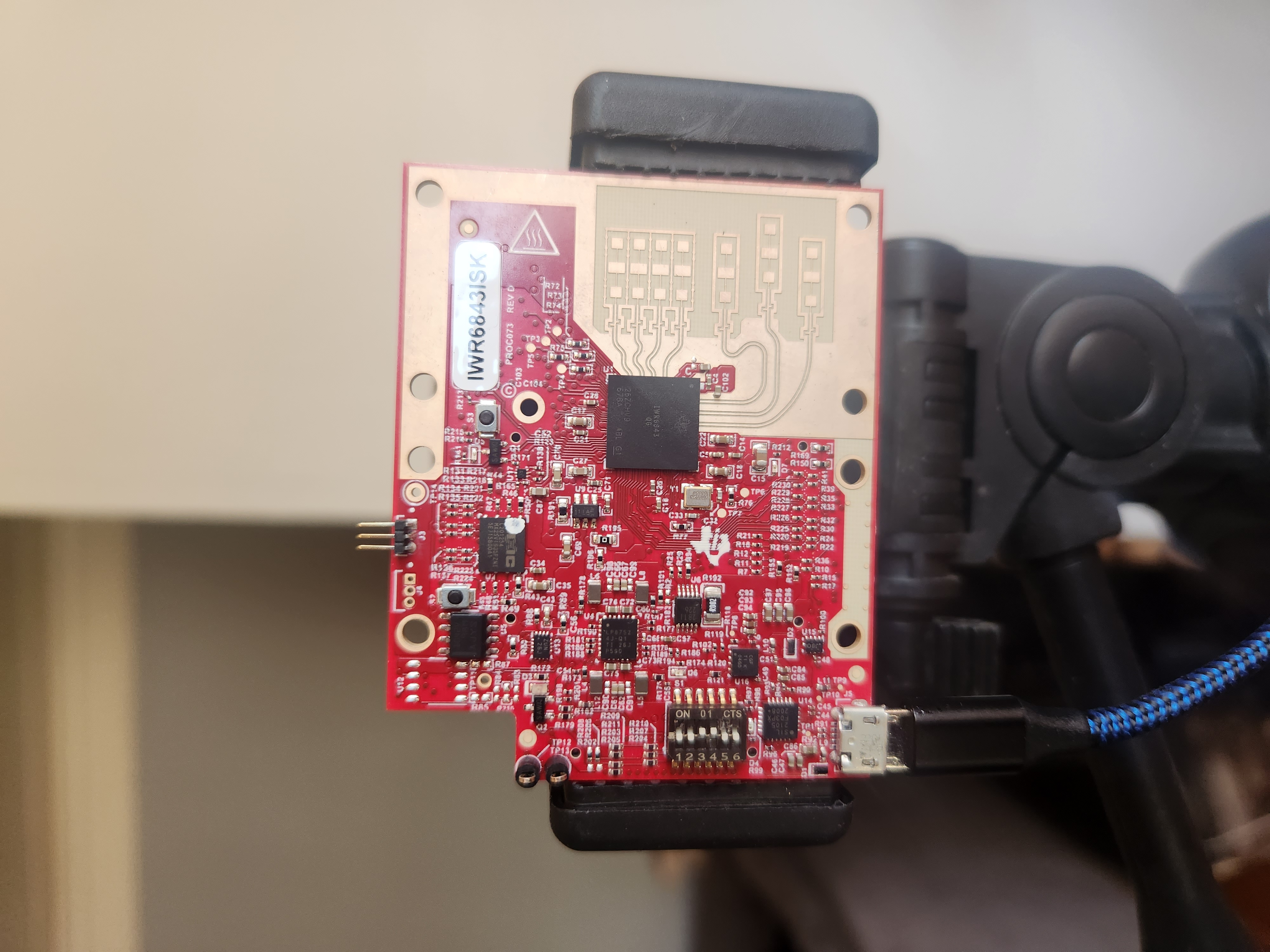
I always though X,Y,Z data Z was the depth, however in the parser scripts it seems as though the Z channel is the elevation or Y in a cartesian plane. It seems strange and defies convention.  If I rotate the antennas, tx so they are oriented vertically, should I swap the x and z coordinates in parser_mmw_demo.py or will this throw off the calculations?  I am intentionally doing this to try and capture as much vertical space as possible. So if you configure the antennas in 2D mode, you will not get elevation data (obviously), just the distance in the x axis and y the depth.  Is this a mistake in the code or should these be treated as somewhat arbitrary variables?  

I need to some more testing but I'm also seeing some wierd data like the sign of the degrees of elevation flipping, it might be related to the math in the  parser_mmw_demo.py

What I'm doing as a test is facing a wall, putting an object on a string and swinging it like a pendulum a couple of feet in front of the radar.  I parse the data and look at the results.  Do I need to calibrate sensor. Where are instructions to do this ?

  • Also does the group track algorithm actually group the same object from frame to frame, so for example Object 0 will be the same for the next frame and the next frame or will it change?  I am also reviewing documentation in /packages/ti/demo/xwr68xx/mmw/docs/doxygen/html/index.html

  • Hi Miguel,

    In response to your first post, please view this piece of documentation in our Toolbox: Understanding UART Output Guide

    We support multiple formats of outputted data, so you may specifically choose the type of processed output you want. For example, look at the Detected Points TLV Payload, it outputs the X,Y,Z coordinates of a detected point relative to the sensor-scene (determined by the sensor position config command), and a doppler velocity. You could also configure a different type of output. For this reason, there is not correct "convention", we provide many options.

    If you are two flip the sensor, antenna geometry needs to stay the same, since it determines the point cloud. The detection layer for point cloud does everything in 'sensor coordinates' so regardless of the mounting, it is always processed the same. Tracking and Visualizer both translate to "world coordinates". That is to say, it is a matter of handling the transformation in the application code.

    To your second post, please refer to 3D_people_counting_demo_implementation_guide.pdf and 

    3D_people_counting_tracker_layer_tuning_guide.pdf for clarification on the gtrack algorithm.
    Regards,
    Luke