This thread has been locked.

If you have a related question, please click the "Ask a related question" button in the top right corner. The newly created question will be automatically linked to this question.

LDC1614: Jumps in output values

Part Number: LDC1614
Hi,

I’m experimenting with a LDC1614 on a custom board with a PCB coil.

While it generally works fine, I get jumps in the output signal when moving towards and away from the target.

To have precise movement I mounted the board to a 3D printer.

The following diagram shows the output values when moving from 15 to 4 and back to 15 mm.

This is very reproducible.
 

I tried also horizontal movement over a slanted piece of metal to ensure that it is not a mechanical problem of the Z-axis. 
I also moved it by hand, and while the output was quite shaky, the jumps were still visible.
The board has a 40MHz crystal oscillator but I tried also with the internal clock with a similar result
(output values in a slightly different range and more noisy).
The oscillation seems fine:  The frequency is quite close to the results from the TI webench. I also measured the resonance frequency of the coil/cap which also matches that. I set the drive current by measuring the output voltage with the oscilloscope and
manually tuning the DRIVE_CURRENT parameter to be in the recommended range.
I tried with channel 0 and 2 with the same results. I dumped the relevant registers for channel 2: 0x0a:0x26a0 0x0e:0x0000 0x12:0x0020 0x16:0x1002 0x18:0x0002 0x19:0x0000 0x1a:0x9601 0x1b:0x020c 0x20:0x9cc0 0x7e:0x5449 0x7f:0x3055 What do I miss?
br
Richard
  • Hello Richard, 

    I have a few clarification questions for you in regards to this issue: 

    • Is there any metal on the 3D print frame that the sensor would move past? 
    • What is the size and shape of the metal target that you are using? 
    • Can you take an oscilloscope capture of the sensor waveform for scenarios around the result jumping? It would be good to see if the frequency of the sensor oscillation is also shifting at that time. 

    It looks like your settings already have the sensor auto-amplitude disabled, but that can also lead to similar behavior as this so it wouldn't hurt to double check that the register is properly getting written and saved to the device. 

    Best Regards, 

    Justin Beigel

  • Hi Justin,

    >> Is there any metal on the 3D print frame that the sensor would move past? 

    >>What is the size and shape of the metal target that you are using?

    The sensor is moving towards the center of the build plate in Z direction. The build plate is a square 350mm steel plate.
    While moving it does nor pass anything on the side.

    I also did some manual tests by moving a small aluminium block on a linear rail by hand which showed similar artifacts.

    >>Can you take an oscilloscope capture of the sensor waveform for scenarios around the result jumping?

    I tried to, but I was not able to see anything useful as these jumps are quite small in relation to the absolute frequency.

    I might need to try again...

    According the registers: What I have posted are already the values I read back, These match the values i have written.

    br

      Richard

  • Hello Richard, 

    Aside from the frequency change being minimal, was there any odd behavior on the sensor amplitude? 

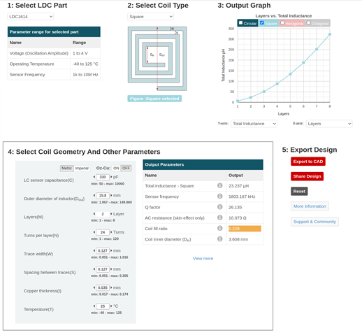
    Additionally, what is the sensor design you are using? Can you share a screenshot of your webench design? 

    Best Regards, 

    Justin Beigel

  • Hi Justin,

    No, there were no visible jumps in amplitude or waveform changes.

    Sure, here we go....

    br

      Richard

  • Hello Richard, 

    Thank you for the additional information. I am still looking into what could be causing this but in the meantime, can you depopulate the capacitors on two of your sensor coils you are not using and then rerun the test? This would be a good way to see if there is any coupling between them in your system. 

    Best Regards, 

    Justin Beigel

  • Hello Justin,

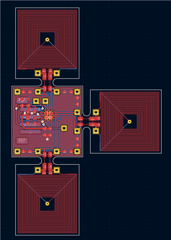
    I cut away 2 coils completely as the board is designed for that.

    Sadly that did not make a difference.

    br

      Richard

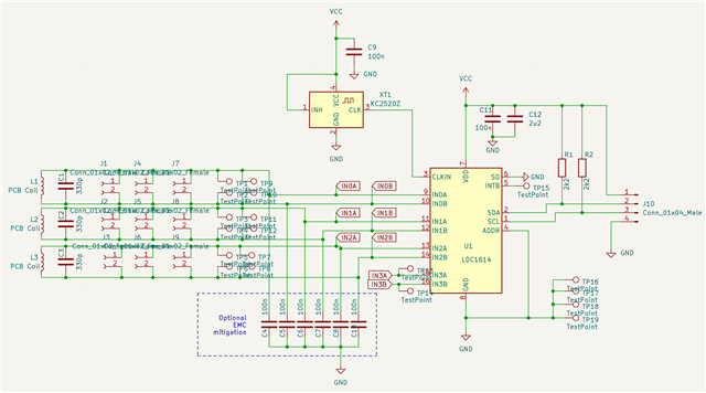
  • Here is the schematics

    Please note:

    Originally I did not populate the EMC capacitors. Later I populated 12pF. This made no difference.

    So please ignore the value of 100nF for them.

    All the connectors and test points in the INxA/B lines are not physical connectors, these are pads on the PCB to allow cutting the coils and attaching them in different ways.

    The 330pF capacitors are populated close to the coil, not on the other side of the cut away slots.

  • Hello Richard, 

    Thank you for the additional information. I discussed this issue with a colleague and we have the followings tests to further debug this issue: 

    • Can you look at your CLKIN signal on an oscilloscope while these jumps occur? Is there any noise on the pin or any unexpected cyclical behavior on your clock waveform? 
    • What happens to your data if you turn the auto-amplitude adjustment feature on? Do the jumps get worse, improve, or stay the same? 
    • Can you test with different RCOUNT settings? I would try at double and half current RCOUNT values. 

    Thank you, 

    Justin Beigel

  • Hello Justin

    I tried already to use the internal clock with a similar result
    (output values in a slightly different range and more noisy).

    Do you think probing the clock still makes sense?

    I'll try the settings you mentioned.

    Many thanks for your efforts!

    Br

    Richard

  • Hello Justin

    I really have to apologize that I wasted your time.

    It was an immensely stupid software bug that I overlooked dozens of times!
    I had a typo where I combined the DATA registers into a 32bit value.

    Thanks for you efforts.

    br

      Richard