This thread has been locked.

If you have a related question, please click the "Ask a related question" button in the top right corner. The newly created question will be automatically linked to this question.

AWR2944: Processing of 1D FFT data to 2D FFT data and demodulation of DDMA

Part Number: AWR2944

Hi Team,

Use the AWR2944EVM to export the uncompressed 1D FFT data and use matlab for process validation. When using data from 1D FFT for 2D FFT, the data is windowed first. After calling the function DPU_DopplerProcHWA_config in the function DPC_ObjectDetection_execute, use memcpy to copy the data from the window to a fixed space on L3 and send that data out for processing using the serial interface. There are some issues:

1) The data for each window is different. Use the following to get the data for window:

Int32_t * window = (Int32_t *)0x88228600, memcpy(window,subFrmObj->dpuCfg.topplerCfg.hwRes.hwaCfg.window+64,768)

Where 0x88228600 is the first address of a space not being used on L3, and +64 is because winRamOffset = 256 bytes. And hwaCfg.window is of type Int32_t*, 768 represents windowSize in bytes. Windows are generated using the function mathUtils_genWindow in the function DPC_ObjDet_GenDopplerWindow, so the resulting window functions should not be different. But why does the window get different? 

2) After windowing the decompressed 1D FFT data and then make 2D FFT in matlab, the result seems to be wrong as follows:
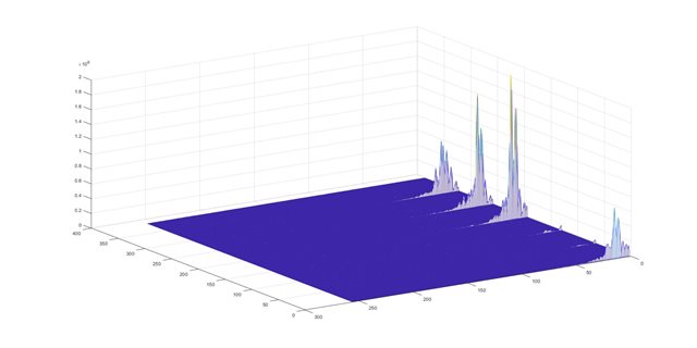
(The 2D FFT result without windowing)
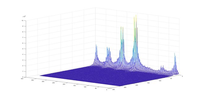
(The 2D FFT result with windowing)

3) Follow the steps to solve for velocity ambiguity on the Matlab to find the maxidx for each rangeBin and dopplerBin from the DDMA metric. The difference was found when compared to the maxidx obtained by the smearing speed on AWR2944. Even though disable the windowing before 2D FFT on AWR2944, it is still somewhat different from the maxidx obtained on matlab.

Is it due to FFT in HWA and other fixed point operations? 

Could you help check this case? Thanks.

Best Regards,

Cherry

  • Hi,

    The customer found that the problem with the exported window data is due to memcpy (window, subFramObj->dpuCfg.doplerCfg.hwRes.\hwCfg.window+64, 768) does not require an offset address of 64. The data is now the same as the hanning window generated on matlab.

    But when you take maxidx, there is about a quarter of the data that is different. is the above point 3 cause this issue?

    There is no assignment to WindowMode in the code, is the real data format of 18bit default? Are the real and imaginary portions of the input Hwa for FFT operations multiplied by this 18-bit data at this point?

    Thanks and Regards,

    Cherry

  • Hi Cherry,

    1. Good to hear that this was resolved!
    2. Is this only with the window generated and taken from the device or even a window generated on Matlab (same window)? Can you share a comparison plot of both the windows?
    3. Can you provide more details on the mismatch? Also, would it be possible to provide a pseudo script of how this was performed on MATLAB. HWA operation can affect the outputs, but the difference should not be huge.

    In addition to this, I have some more questions:

    • Which version of the SDK is being used?
    • Is the device revision ES1.0 or 2.0?
    • Are there any paramset changes done?

    Regards,

    Kaushik

  • Hi Kaushik,

    Thanks for your support.

    Is this only with the window generated and taken from the device or even a window generated on Matlab (same window)? Can you share a comparison plot of both the windows?

    When the 2944 generated window is exported, it is compared to the hanning window generated on matlab without any difference. 

    Can you provide more details on the mismatch? Also, would it be possible to provide a pseudo script of how this was performed on MATLAB. HWA operation can affect the outputs, but the difference should not be huge.

    As configured by the Hwa, the 1D FFT data from 2944 is windowed, log2abs are taken, DDMA METRIC is taken, perform a DDMA de-blur operation as follows: 

    a. The result after the window is added divided by 2^17 and rounded,  is described here in the 2944TRM as ''the output of this multiplication is rounded back to 24-bit I and 24-bit Q by dropping excess LSBs. It is not specified how many bits of LSB are discarded, where 2^17 was tested multiple times to obtain. 

    b. The 2D FFT is applied to the windowed data, because dstScale = 0 for the 2D FFT in the Hwa configuration, the result of the 2D FFT is multiplied by 2^8. 

    c. Log2abs processing of the result of the second step, because the Hwa configuration here has srcscale=8, so divide the result of the second point by 2^8 as input, and the output data format after log2 is 16bit. Where 5bit is an integer and 11bit is a decimal place. The result of log2 is normated by the function quantizer('fixed','round',[16,11]), and finally the result of log2 is converted to a shaping by 2^11.

    And here's a question, use the JPL (Levitt and Morris) approximation on the 2944 to obtain the ABS value and log2 (N) = k + log2(1+f) from the LUT. Is there a difference with using ABS, log2 on matlab? 

    d. Sum RX, accumulates on the Rx dimension for the results in step 3. Because dstScale = 2 here; so the output needs to be divided by 2^2; 

    e. Using the output from step 4 to obtain DDMA metric, add the energy values of four consecutive TX starting at TX=1,2,3,4,5,6 in matlab to obtain DDMA metric. To align with the Hwa of the AWR2944, dstScale = 0 here, Output is 32-bit data, so multiply the resulting DDMA METRIC by 2^8; 

    f. Based on the results of the DDMA METRIC, the index of the maximum value for each dopplerBin of each rangeBin is evaluated, i.e. maxidx. Differences were found between the maxidx processed on the 2944. 

    The following files are DDMA metric and mapidx data on a rangeBin in the same frame for 64 dopplerBin with 2944 processing result with _2944. _Matlab is the result of the processing of matlab. 

    https://e2echina.ti.com/cfs-file/__key/communityserver-discussions-components-files/118/data.rar

    Which version of the SDK is being used?

    4.3.1.

    Is the device revision ES1.0 or 2.0?

    ES2.0.

    Are there any paramset changes done?

    Only the value of twidDitherEnable was modified to be HWA_feature_bit_disable before making 3D FFT.

    Also, is there a script for simulink for MATLAB of Hwa for AWR2944 for reference? 

    Thanks and regards,

    Cherry

  • Hi Cherry,

    Thank you for your input. I would like the customer to try the following:

    1. Feed the decompressed data on PC side as the input to 2D FFT on the device. (Simple breakpoint at EDMA transfer trigger and directly load into decompressed buffer on L3). Ideally, this would have to match as your inputs are the same in both cases. If it does match, you might have to look at your decompression step. Are you using your own script for that?
    2. Enable the dither for 1D FFT and compression.

    Please note, that there will be some difference in the way FFT is computed on HWA vs that on matlab (Fixed vs Float).

    And here's a question, use the JPL (Levitt and Morris) approximation on the 2944 to obtain the ABS value and log2 (N) = k + log2(1+f) from the LUT. Is there a difference with using ABS, log2 on matlab? Yes. It will be an approximate version of the same on the HWA when compared with MATLAB and it was done to reduce the number of cycles.

    There is also a known issue with the Advanced mag block that introduces a small error (in the LSBs) in the input samples (This cannot be bypassed in hardware). This error could cause a potential mismatch in the maxidx.

     Is there a script for simulink for MATLAB of Hwa for AWR2944 for reference? -> No. We do not provide a simulink script HWA.

    Regards,

    Kaushik

  • Hi Kaushik,

    1) The data used by the customer is 1DFFT data decompressed on the 2944. They have also taken 2D FFT data on a range unit of the same frame data, and there are some differences between the 2D FFT results calculated on matlab using 1D FFT data, which should be due to the difference between Fixed and Float of the FFT. 

    2) Maxidx mismatches persist when twiddither is enabled. However, during the testing, it was found that the mismatch between the matlab results of maxidx and the 2944 results was mostly the range and Doppler units where the noise floor of the clutter was found, which had a power of about 6 subbands and were more affected by rounding or truncation errors.

    Now rangeBin*DopplerBinTotal=16384, only about 400 bins have maxidx mismatch. Can I assume that this maxidx mismatch has no or limited impact during the actual target detection? 

    Thanks and regards,

    Cherry

  • Hi Cherry,

    Your observations are right. The maxidx mismatch could potentially have a mismatch but can be mitigated. Can you ask the customer to try once with the following correction (upon the FFT results and on the input to the max block if possible):

    1. Enable the CMULT mode 5 (Scalar multiplication)

    2. Program 525314 as the scalar to be multiplied. (256/511)

    3. Apply a 2x scaling using the input formatter.

    This should give you a correction on the input by 512/511 which should reduce the error due to the magnitude block.

    Please let me know how it goes on the customer's end once this is tried out.

    Regards,

    Kaushik

  • Hi Kaushik,

    Thank you and the customer tried the #1:

    It should still be Enable the fault mode 0. Multiply all inputs by IScale[0] and QScale[0]. The customer assign the values of IScale[0] and QScale[0] to 256/511 respectively, and then put the input *2 of the 2D FFT by having srcScale=7. The results of testing in the same environment show that the number of maxidx mismatches has been reduced from about 400 to about 200, which, although improved, still does not match the processing results of 2944 exactly with matlab.

    Is it ok to just ignore this portion of the mismatched maxidx? Because they typically appear in noise cells that do not have a target. 

    Thanks and regards,

    Cherry

  • Hi Cherry,

    Even 200 mismatches in the detection list are quite high and the workaround should have reduced that number significantly regardless of whether they happen to be in the noise region.

    • Has the customer been able to isolate the number of mismatched indices just to this particular block?
    • Is it possible to quantize the mismatched indices? How large is the variation from the actual results?
    • Does the customer have any filtering algorithm going forward to discard the mismatched indices in noise region? If this is working out well, the previous problem can potentially be ignored.

    Regards,

    Kaushik