This thread has been locked.

If you have a related question, please click the "Ask a related question" button in the top right corner. The newly created question will be automatically linked to this question.

IWR1843BOOST: SPI Slave Operation (3-Pin vs 4-Pin Mode)

Part Number: IWR1843BOOST

Hi,

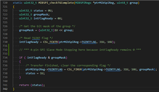
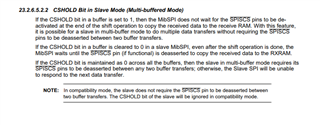
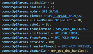
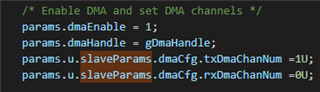
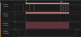
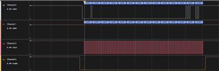
I am busy setting up SPI (slave mode) on a IWR1843BOOST board to prototype SPI communications we wish to do. I have read through the doxygen files as well as the test examples. To test my code, I have set up a STM32 Nucelo board as a SPI master. When using 3 pin mode (SPI_PINMODE_3PIN) my code operates correctly and I am able to read data from the master. However, when in 4 pin mode (SPI_PINMODE_4PIN_CS) the code either hangs, or times out depending if I include a transfer timeout or not. I presume the code is waiting for a HW signal that I know is being sent (confirmed with logic analyser - see picture below) and I am sure that I have the pinmux settings correct (see below). I am therefore at a loss as to why the 4-pin mode isn't working and am hoping someone on this forum can point me in the right direction? I will be happy to share more code as/if required.

A further question I have, is does the driver support multiple reads for a single write? That is, let's say I send 12 bytes of data with a single SPI master write operation and want to read the first two bytes, do something with them (very quickly) and then resume reading the remaining 10 bytes. I haven't managed to get this working either. I am able to read the first two bytes (in 3-pin mode), but when I try read the remaining 10 bytes using the SPI_transfer function, the code waits forever and only resumes when a new SPI write operation is initiated by the master.

Thank you in anticipation.

/* SPIA_MOSI */
Pinmux_Set_OverrideCtrl(SOC_XWR18XX_PIND13_PADAD, PINMUX_OUTEN_RETAIN_HW_CTRL, PINMUX_INPEN_RETAIN_HW_CTRL);
Pinmux_Set_FuncSel(SOC_XWR18XX_PIND13_PADAD, SOC_XWR18XX_PIND13_PADAD_SPIA_MOSI);

/* SPIA_MISO */
Pinmux_Set_OverrideCtrl(SOC_XWR18XX_PINE14_PADAE, PINMUX_OUTEN_RETAIN_HW_CTRL, PINMUX_INPEN_RETAIN_HW_CTRL);
Pinmux_Set_FuncSel(SOC_XWR18XX_PINE14_PADAE, SOC_XWR18XX_PINE14_PADAE_SPIA_MISO);

/* SPIA_CLK */
Pinmux_Set_OverrideCtrl(SOC_XWR18XX_PINE13_PADAF, PINMUX_OUTEN_RETAIN_HW_CTRL, PINMUX_INPEN_RETAIN_HW_CTRL);
Pinmux_Set_FuncSel(SOC_XWR18XX_PINE13_PADAF, SOC_XWR18XX_PINE13_PADAF_SPIA_CLK);

/* SPIA_CS */
Pinmux_Set_OverrideCtrl(SOC_XWR18XX_PINE15_PADAG, PINMUX_OUTEN_RETAIN_HW_CTRL, PINMUX_INPEN_RETAIN_HW_CTRL);
Pinmux_Set_FuncSel(SOC_XWR18XX_PINE15_PADAG, SOC_XWR18XX_PINE15_PADAG_SPIA_CSN);

/* SPI_HOST_INTR - not used, reference code */
Pinmux_Set_OverrideCtrl(SOC_XWR18XX_PINP13_PADAA, PINMUX_OUTEN_RETAIN_HW_CTRL, PINMUX_INPEN_RETAIN_HW_CTRL);
Pinmux_Set_FuncSel(SOC_XWR18XX_PINP13_PADAA, SOC_XWR18XX_PINP13_PADAA_SPI_HOST_INTR);

  • Hi,

    What version of the SDK are you running?

    Have you tried running the SPI tests located: <SDK_3.xx_INSTALL_DIR>\packages\ti\drivers\spi\test\xwr18xx ? Are you able to get them working?

    With regards to your second question about multiple reads, please allow me 24 hours to find an answer for you. You can look in the Technical Resource Manual here and it might be able to give an idea: https://www.ti.com/lit/ug/swru522e/swru522e.pdf?ts=1683838051348&ref_url=https%253A%252F%252Fwww.ti.com%252Fproduct%252FIWR1843 

    Regards,

    Tim

  • Hi Tim,

    Thanks very much for the prompt reply. To answer your questions:

    • I am using SDK: mmwave_sdk_03_06_00_00-LTS
    • I have gone through the SPI driver examples very carefully, but haven't actually tried running them on the board - I shall do so shortly

    It feels to me that maybe I have not set up the SPI pins correctly and the board is expecting a CS signal that I know is being sent, but perhaps isn't being handled correctly with my setup? If it helps, this is exactly where the code is stopping when it reaches "if ( intFlagReady & groupMask)" in mibspi_dma because intFlagReady remains zero (see below)

    Thanks very much, I shall look in the manual so long, but will appreciate your response once you have had a chance to look into my question more.

    Regards,

    Alan

  • Hi Tim,

    I managed to get the 4-pin mode working. It seems that adding the below line to my SPI parameters fixed it for some reason.

    • spiParams.u.slaveParams.chipSelect = 1;

    Regards,

    Alan

  • Hi Alan,

    That's great news! Are you still having issues with multiple reads? I am still looking into that, so please allow me until Monday to get a definitive answer for you.

    Regards,

    Tim

  • Hi Tim,

    Sadly not. I still need to perform a separate SPI read for every SPI write.

    No problem. I'll appreciate your feedback once you've had time to get a definitive answer.

    Thanks and Regards,

    Alan

  • Hi Alan,

    Sorry to hear. Thanks for your patience, and I will get back to you Monday!

    Regards,

    Tim

  • Hi Alan,

    Quick follow up question with regards to the SPI reading, have you tried simply reading all 12 bytes and processing them afterwards? Is there a reason you need to split up the reads?

    Regards,

    Tim

  • Hi Tim,

    We have tried reading all 12 bytes at once and can read them correctly. We split the reads, because the length of the transfer can vary, depending on what message we send. We thus use the first read to give us information about the second read - like how much data is remaining - before we perform it.

    Regards,

    Alan

  • Hi Alan,

    Thank you for the reply. Have you looked into the TRM that I sent above? I was able to find information about setting a CSHOLD bit when in multi-buffered, slave mode. See page 2892 of the TRM and the picture below:

    This may not be what your looking for, but it might help to point in the right direction.

    Another thing to maybe try is putting a delay after the first 2 bytes are sent from the master. This may stop the code on the slave side from hanging after reading the first 2 bytes.

    I'll keep looking into this, however. Let me know any updates from your end.

    Regards,

    Tim

  • Hi Tim,

    Thanks for this info. I have started going through the manual, but have not had success yet, unfortunately.

    With regards, to your suggestions above, I haven't had success yet either. To confirm, I enable multi-buffered mode with "#define SPI_MULT_ICOUNT_SUPPORT" and the below are the parameters I use:

    Hopefully it is possible, and I am just missing something basic?

    Regards,

    Alan

  • Hi Alan,

    1. Another resource to checkout is the datasheet for the device: https://www.ti.com/lit/ds/swrs236b/swrs236b.pdf?ts=1684350812301&ref_url=https%253A%252F%252Fwww.ti.com%252Ftool%252FAWR1843BOOST

    On page 49 there is a typical interface timing diagram for the device in Slave mode with a couple of assumptions from the host. There is probably no new information here for you. Something interesting to note is that the CS bit should be toggled every 2 bytes. It seems setting it to 1U solved your previous issue, but maybe toggling it instead of just holding it at 1U could change something.

    2. Looking in <SDK_INSTALL_DIR>\packages\ti\drivers\spi\test\common\test_common.c I've found you must also set the tx/rxDmaChanNum as seen below:

    I will continue to look into it and let you know if I find something in the meantime.
    Regards,

    Tim

  • Hi Tim,

    Thanks for this further information. I will try some of your suggestions tomorrow. For now, I just wanted to let you know that I do set the dma channels exactly as you suggest elsewhere in the code. Apologies for not making this clear in my previous post.

    Regards,

    Alan

  • Hi Alan,

    Thanks for the response, I see. Let me know if you are able to get anywhere tomorrow.

    Regards,

    Tim

  • Hi Tim,

    Still no luck unfortunately.

    Below is a picture of the 10 bytes of data I send from the controller (unfortunately we will likely not be able to toggle CS every 2 bytes).

    I initially do a SPI_Transfer call to read the first 2 bytes {0x01, 0x01} which works correctly, then I do a second SPI_Transfer call to read the remaining bytes {0x00, 0x00, 0x00, 0x00, 0x00, 0x00, 0xA5, 0xA5} and it times out. I use the same SPI_Handle (that isn't closed after the first transfer) to call the SPI_Transfer function each time as follows:

        //... Setup code above
        
        SPI_Transaction spiTransaction =
        {
            .count = 2, // Initially 2, then 8 for second call
            .txBuf = NULL,
            .rxBuf = spiRxBuffer,
        };
        
        SPI_transfer(spiHandle, &spiTransaction1)
        
        //...

    After the first read, I had a look at the stats output by the transfer, and interestingly there seems to be an rx over-run of 5 for the clock cycle I am using (~6MHz)? See below.

    I will keep digging into this, but would appreciate any further insight if you have any please. I guess the main question is, is what we are intending on doing even possible with the SPI drivers we are using?

    Regards,

    Alan

  • Hi Alan,

    I've consulted further with our SDK team on this. It is doubtful that it is possible with our SPI drivers. The only chance might be if you are able to get the CS toggled every two bytes as mentioned above.

    I can continue to look into it further, but please know that it is probably doubtful to accomplish.

    Regards,

    Tim

  • Hi Tim,

    Thank you for this feedback. We will see what we can do on the controller side, or change our implementation to be more inline with the TI SPI drivers. Thanks for all your help on this question.

    Regards,

    Alan