Because of the holidays, TI E2E™ design support forum responses will be delayed from Dec. 25 through Jan. 2. Thank you for your patience.

This thread has been locked.

If you have a related question, please click the "Ask a related question" button in the top right corner. The newly created question will be automatically linked to this question.

AWR6843AOPEVM: AWR6843AOP Execution time calculation

Part Number: AWR6843AOPEVM
Other Parts Discussed in Thread: AWR6843AOP

Hello amazing TI community,

Enjoying my project and asking questions here. For that, I need to estimate the execution time needed by the radar to capture a data, process it and give an output. 

I have worked with many microcontrollers where counters were set up for this purpose (to estimate timings), however in the AWR6843AOP datasheet I cannot find any mention of a counter or time register (beside the clock). 

Could anyone please enlighten me on a way to do that ? I only need a WCET of the basic radar function which is produce an output on the EVM board.

Many thanks to you all Slight smile

Lilia.

  • PS : Or is it an already available data ? is there an information already given by the manufacturer about this timing.

    Thanks again !

  • Hi Lilia,

    The data you are looking for is most likely sent as a TLV over UART from the device. Take a look at the Understanding UART Data Output Format here:https://dev.ti.com/tirex/explore/node?a=1AslXXD__1.00.01.07&node=A__ADnbI7zK9bSRgZqeAxprvQ__radar_toolbox__1AslXXD__1.00.01.07 

    The "Statistics" sections should have data that can help.

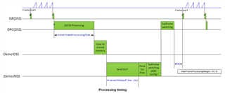
    Also, if you look at the diagram in <SDK_INSTALL_DIR>/packages/ti/demo/xwr68xx/mmw/docs/doxygen/html/index.html under "Stats Information" You can see a chart depicting how the data from the TLVs can be used to calculate execution time.

    Hopefully this points you in the right direction.

    Regards,

    Tim

  • Hi Tim,

    Thanks for the valuable answer, indeed I will be using the stats info TLV to get my timings which is great :)

    However, based on the figure below found in the stats information you refered to, I would have a few questions :

    1- My main goal is to calculate the time needed by the radar to produce an output, looking at the diagram below, it means all I need is the chirp time and the interFrameProcessingTime (which I can have through the TLV). 

    For that how can I configure/determine the chirp time ? I am currently exploring this document mmwave sdk user guide to set the radar configurations, however I cannot find anything explicit about this timing. Any clues ?

    2- In my project, I am setting the frame period to 30Hz (33.33ms), since a frame period goes from one start to another, I can always be sure that the timing I am looking for will be lower than 33.33ms ? Can you confirm please.

    3- Another question regarding the subframes, in my configuration I set the dfeDataOutputMode to 1 (legacy mode) ie I am not enabling the advFrameCfg to specify a number of subframes, does this mean that I automatically get no subframes ? does it induce no subframe switching time ?


    Thanks and regards,

    Lilia.

  • Hi Lilia,

    1. I would recommend looking at our Sensing Estimator located at: https://dev.ti.com/gallery/view/mmwave/mmWaveSensingEstimator 

    It should give you a better understanding of your chirp configuration.

    2. I am not certain, you should look at the TLV's mentioned above when running the device to ensure they are less than your 33.33ms, though based on the diagram above and my understanding, yes it should be less.

    3. I can check on this and have a response for you by Monday, but I believe there would still be subFrame switching time even if you are in legacy mode.

    Regards,

    Tim

  • Hello Tim,

    Thanks for the reply once more. I have some new questions while trying the mmWave sensing estimator link.

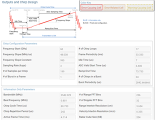
    1- While configuring the radar, in the basic chirp config, as you can see below, the values are compliant. 

    Tc = idle time + ramp end time = 7+73.733 = 80.733 us (that can be found in the information only parameters) (*)

    Active Frame Time = chirp repetition period * Num of chirps = 242 * 17 = 4114 us

    However I still cannot figure out how the chirp repetition parameter is found ?

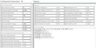
    2- When I send this config to the advanced chirp design, I get a different chirp time Tc as shown below : 

    Tc = 66.333 us rather than 80.733 us found earlier. Why is this ? equation (*) should remain the same, isn't it ?

    3- I would also like to confirm some expressions (found by guess work or in the answer here Ti forum answer) and definitions :  

    Active frame time  compliance chirp = RF duty cycle * frame periodicity = Tr * N chirps 

    Frame periodicity (in unit of time) = Active Frame time + Idle Frame time (Nothing happens on the device until next frame trigger)
    Active Frame time = Total chirping time + computation time (if there is signal processing done on the data)
    Total Chirping time = number of loops * number of chirps in a sequence * (Active chirp time + Idle chirp time)

    What do the active frame time and active chirping time represent ?

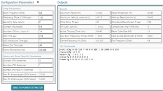
    4- Finally, when adding an old config made through the mmWave Demo Visualizer, I get really weird values of Tc and Tr as shown, what is the problem ? is the configuration incorrect ?

    Ps : an out of curiosity question

    When configuring the radar, I have a question regarding the txChannelEn that takes the transmit antenna mask as a value. If the value is set to '0', I get to use one Tx antenna, however I get no chirp with it. Could you please enlighten me on how this works ? what kind of signal is emitted ? 

    I know it's a lot of questions, and will be glad to get answers to as much as possible.

    Thanks in advance?

    Lilia.

  • Hi Lilia,

    1. Chirp repetition parameter should be calculated as num_tx*(idle_time+ramp_end_time)

    2. You'll see in the advanced tab - chirp time is defined as number of samples / sampling rate. In the basic tab, chirp cycle time is ramp_end_time + idle_time_minimum, so they should be different.

    3. In the Sensing Estimator tool, if you hover your mouse over any of these parameters, it should give you a quick definition of what they represent. You can also look in our SDK/Toolbox for those terms as well - they will be defined in there too.

    4. I'm not seeing anything out of the ordinary for Tc or Tr. If the Sensing Estimator tool is not throwing any warnings or errors, those should be valid values.

    5. You should use a value of 0x001 to use just one TX antenna. The value for txChannelEn is 0x111 when to use all 3 because there are 3 1's. E.g.  0x101 will use the first and third TX antennas.

    Regards,

    Tim