This thread has been locked.

If you have a related question, please click the "Ask a related question" button in the top right corner. The newly created question will be automatically linked to this question.

PGA900: Nothing happens when trying a SPI connection

Part Number: PGA900
Other Parts Discussed in Thread: USB2ANY, TS5A23159

Hello,

I linked this post to the other one because I'm basically in the same situation with the same setup. I'm trying to communicate with SPI between the PGA900 and my PC using a C232HM-DDHSL-0 cable from FTDI.

I wrote a code for the PGA where I initialize the SPI settings directly at the beggining of the main.c file (PIN_MUX set for SPI, SPI enabled in DIG_IF_CTRL, COMBUF RX interrupt enabled in COM_RX_INT_ENABLE register). I'm also using an XDS probe with CCS to program the PGA on the EVM board, and I connected the USB to SPI cable for the Master on the USB2ANY port pins.

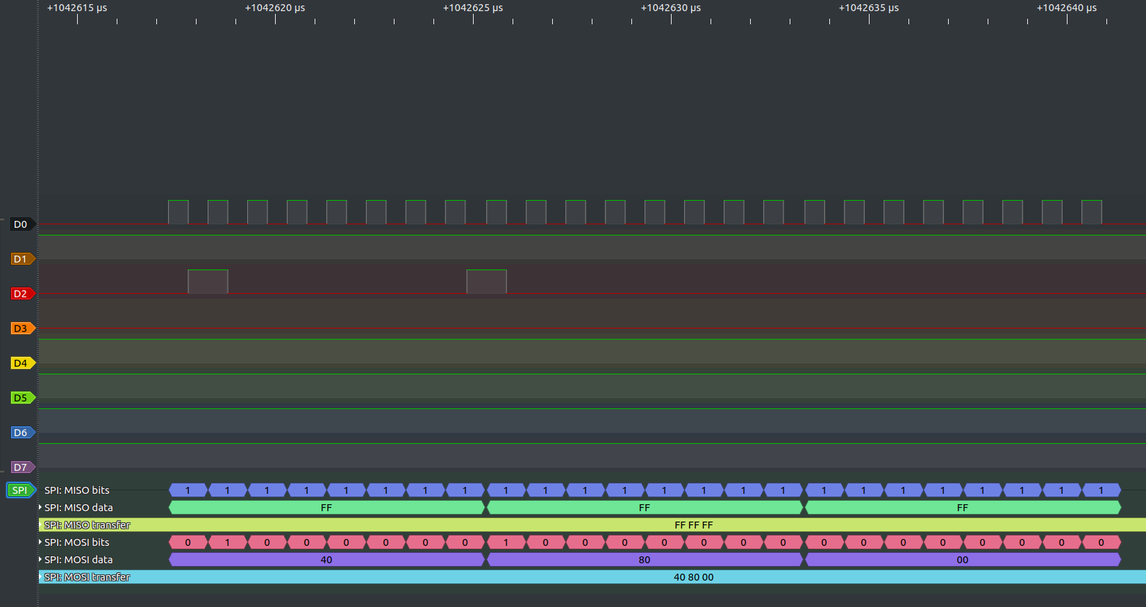
My issue is that whenever I send a message from the Master to write on or to read the COMBUF registers while the MCU is running, I don't get any reaction from the PGA : the interrupt isn't triggered, the data from the Master's message isn't written in COMBUF, and the "answer" the Master receives from the PGA is a message with only 1s. I checked with a logic analyzer, and the MISO pin is always on a high state since the moment is was connected to the master cable.

This time I'm lost, I read the datasheet part on the SPI several times, and checked my hardware connections a dozen times. I'm sure my code for the Master chip is working correctly, so there must be something wrong with the PGA. Do you have an idea of what could be wrong here ?

Have a nice day,

Benjamin.

  • Hi Benjamin,

    If I understand you correctly, it sounds like COMBUF interrupt isn't being triggered. Is this the case?

    The COMBUF interrupt is the most important issue that I can actually help with. What the PGA900 does after the COMBUF interrupt is triggered is determined by you and falls under the category of a Firmware question where I can't help too much, unfortunately.

    The COMBUF interrupt is generated when the COM_DIF_TO_MCU register is successfully written to. Have you put the PGA900 (M0 MCU) into reset (using the MICRO_INTERFACE_CONTROL register) and verified your SPI transactions work? If it does, you should be able to change the address to write to the COM_DIF_TO_MCU register (B1 and B2) and read from COM_RX_STATUS to verify a interrupt was triggered. You'll need to make sure the interrupt in enabled in your base FW (which is what the related question and thread you've linked is doing).

    Best,

    -Cole

  • Hello Mr Macias, thanks for your answer.

    Yes that is part of my issue : the interrupt isn't triggered when I send a message from the master. But I believe my issue is larger than that : when I put the controller in reset mode (or running mode, it behaves the same), and set the Master to write on the COM_DIF_TO_MCU or MICRO_INTERFACE_CONTROL registers (which should always be accessible to write), nothing happens. No interrupt, nothing on the MISO line, and most importantly, the content of the registers isn't changed like it should have (I see their content with the XDS debug probe).

    That's why I'm not sure if it is a firmware issue : technically, I've set up everything in my code to get the SPI to work (at least, everything mentionned in the datasheet of the PGA900), and I still don't get anything, the PGA behaves like it is not set for using the SPI. Weird.

    Anyway, I'll continue to try and test things, but I genuinely have no idea of what I could be missing here.

    Best regards,

    Benjamin.

  • Hi Benjamin,

    To clarify, reads don't give anything on MISO PICO, right? Correct me if I'm wrong but you haven't verified that any of the SPI commands actually work.

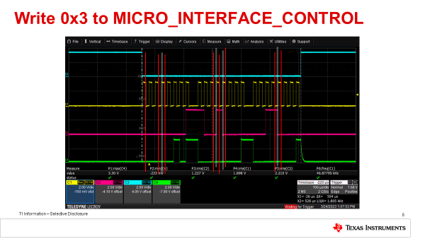
    Here's what my SPI write waveform looks like. Might be good to compare against your waveforms. Note MOSI = PICO and MISO = POCI. 

    I'll need to double check something in the lab in the mean time. Hope to follow up towards the end of the week.

    Best,

    -Cole

  • Hi,

    Sorry for the time I took to answer, I wasn't available last week.

    I'll try to clarify ; the data sent from the Master/Controller on the MOSI/PICO line is visible and correctly sent, I'm sending from my computer some SPI commands like the one you showed. But no matter what message I send, I don't have any reaction from the PGA, even though I have initialized the registers correctly according to the datasheet and other posts on E2E (like I explained earlier, no interruption, no answer on the MISO/POCI line etc...). It's like the Cortex M0 isn't seeing the data I'm sending, and I can't find why it behaves like that. I don't have any waveform available right now, I'll send one as soon as I can.

    Best regards,

    Benjamin.

  • Hi Benjamin,

    No problem, I didn't get to check the thing I wanted in the lab either.

    Anyways, if the MCU is successfully in Reset, you send a read command, and you don't at least get the 0x05 on the POCI line in the first byte, then:

    • The device was never in Reset
    • SPI isn't enabled for some reason
    • or The SPI format isn't correct (e.g. some timing spec isn't correct)

    See if you can get a waveform. That'll help us narrow it down.

    Best,

    -Cole

  • Hi again,

    I did acquire some waveforms with a logic analyser. Here are my testing conditions :

    - I program the PGA with my built code using CCS and a XDS probe, and then put it in run mode using the "resume" button

    - I setup my logic analyser with a sampling frequency of 24MHz (so much higher than the Frequency of the PGA's clock, which is set to 1MHz)

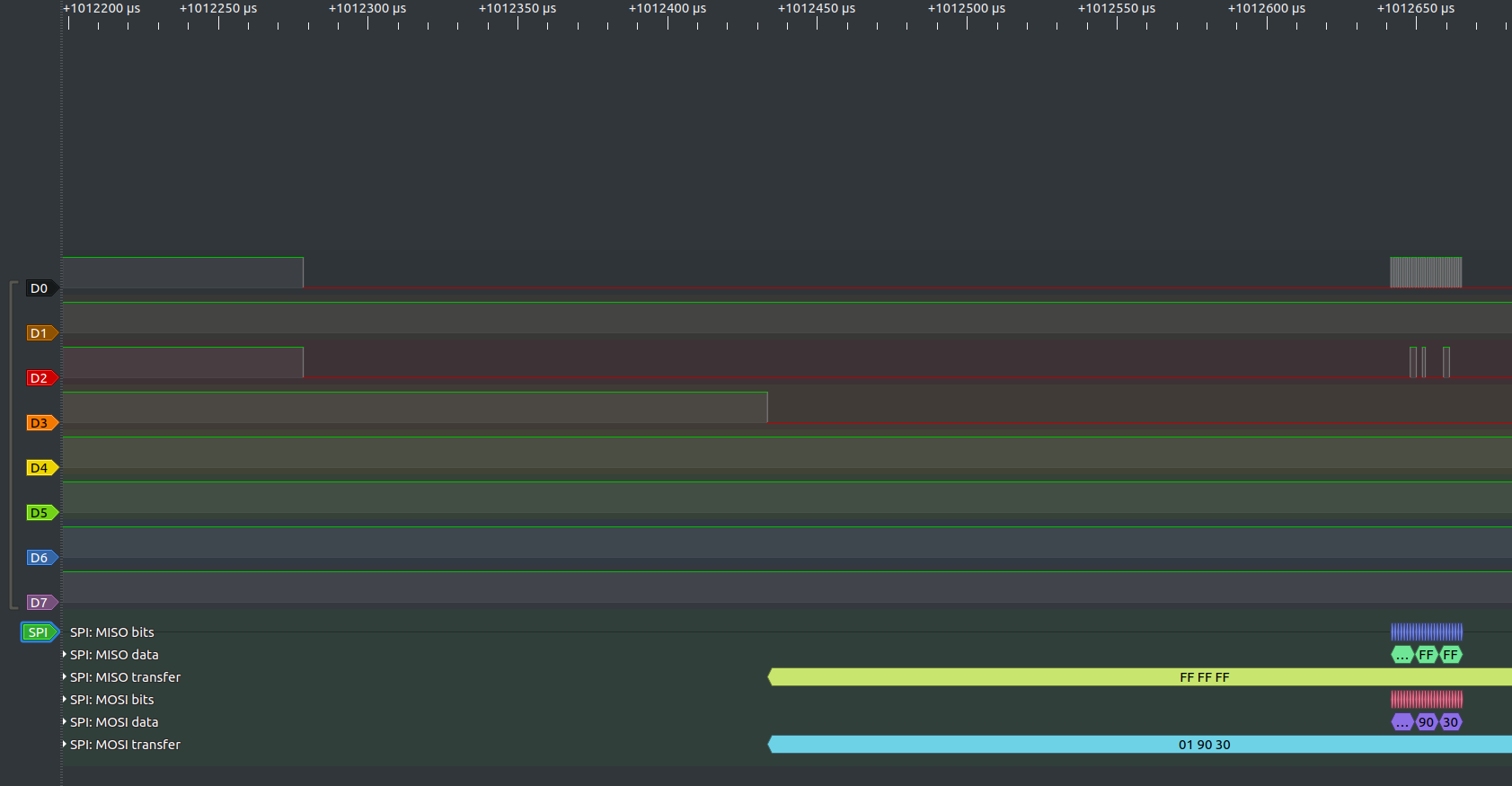
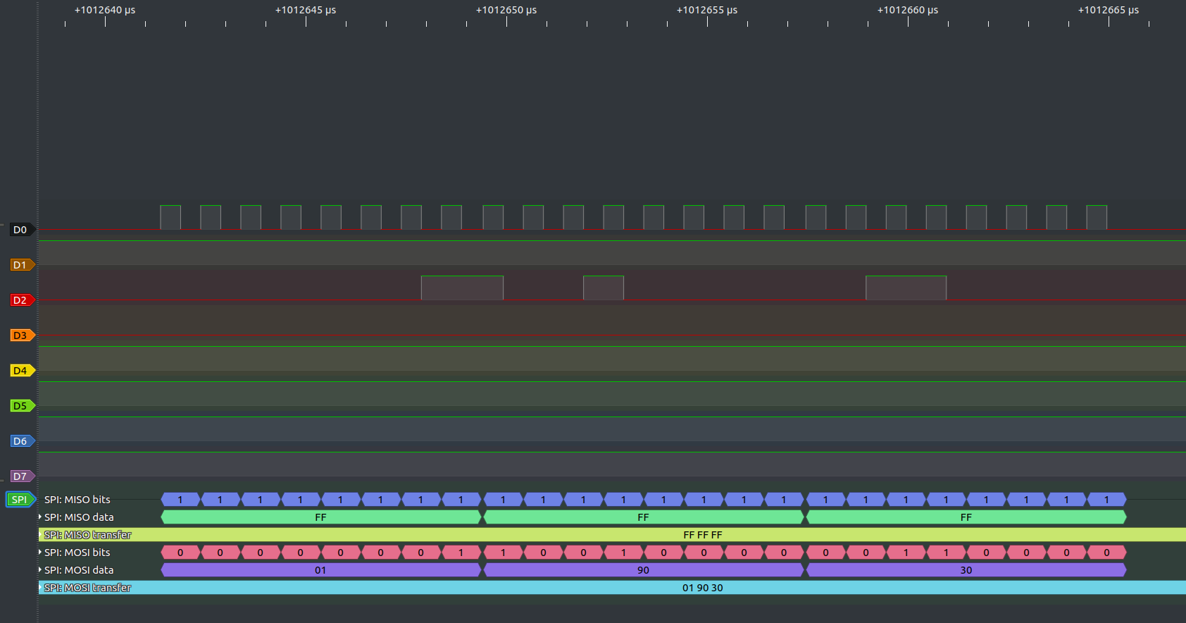
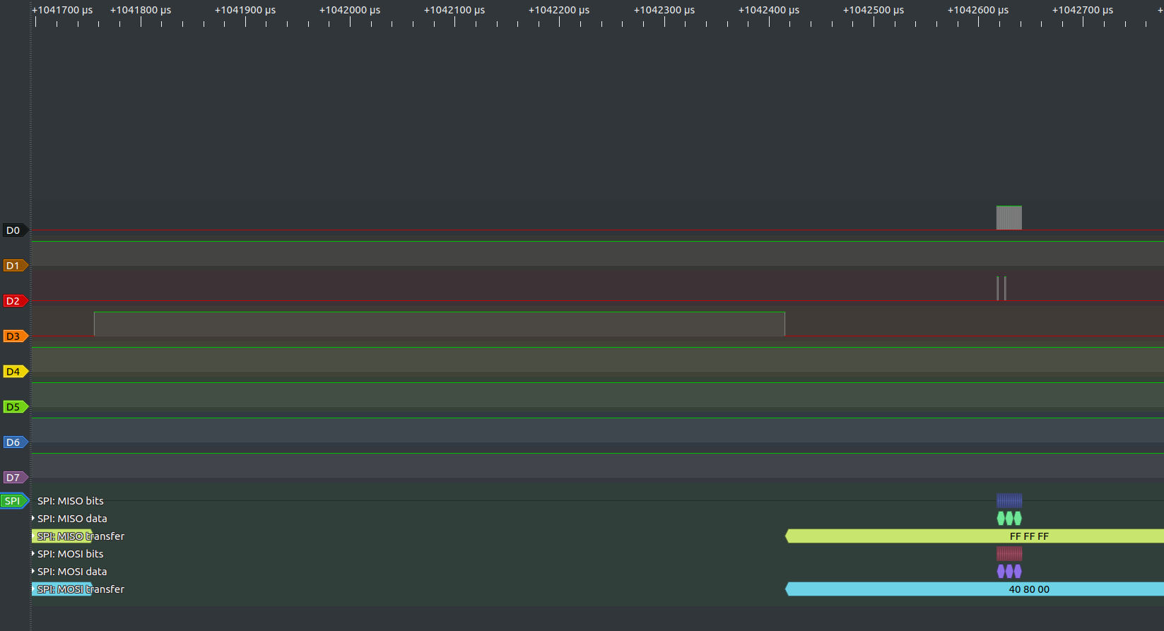
    - I then initialise my master USB cable with a program that does the following : First send a Write order to write 0x03 onto the MICRO_INTERFACE_CONTROL (like the one you showed above), Then sending repeatedly in a loop Read requests to read the content of CLK_CTRL_STATUS (it's just for testing, I want to see if the PGA, while in reset mode, actually answers me with the register's content).

    I get the following behaviour : on the SPI lines the first message from the Master/Controller is sent correctly, but the PGA doesn't answer nor does it enters a reset state. Then, when I send the read requests, it has the same behaviour : no answer, it's like it doesn't react at all to the SPI messages.

    I included a few screenshots of the waveforms ; the first and second are the first message to reset the PGA (one where we see the moment the CS line is pulled down, and the other where I zoomed on the moment the message is sent). The 3rd and 4th pictures are showing the second message I sent in a similar way (large view and zoomed on the message sent). On those pictures, D0 is the clock, D1 the MISO/POCI line, D2 the MOSI/PICO line, and D3 the CS line.

    Let me know if it helped you understand or see something I missed. For now, I think the PGA behaves like the SPI isn't initialized, which is weird because it should be with the code I upload and run on it.

    Best,

    Benjamin.

    Figure 1 :

    Figure 2 :

    Figure 3 :

    Figure 4 :

  • Hi Benjamin,

    Thanks for the data. It looks okay on a logic analyzer at a high level. An oscilloscope will help later, but for now let's do some other checks.

    Any reason why your PICO is high indicating 0xFFFF, etc? It is low in my picture. Do you have a pull up on that line or something? Perhaps another device on your SPI line that is holding it high and PGA can't drive that node low?

    Is your COM_RXRDY_INT_EN bit enabled in your firmware? In addition,  would make sure DIG_IF_CTRL has SPI_EN set as well. Its supposed to be set by default but I would hate to see that not be the case.

    Best,

    -Cole

  • Hi Mr Macias,

    When you're saying "PICO is high", I suppose you're talking about the D1 line on my logic analyser, so it would be the POCI line, right ? (or MISO with the old names). As for a reason it stays at a high state, I don't have any : On my setup, I have the PGA on its EVM board, my USB cable which acts as a Master (or Controller if you prefer the new names for SPI) connected to the EVM on the right pins, and my Logic Analyser plugged on the middle of the lines to monitor them. No pull-up resistors or other devices anywhere, that's why I don't get why the PGA doesn't drive this pin low to communicate.

    As for the registers, I can confirm that in my code over on the PGA the registers are correctly initialized : COM_RX_INT_ENABLE has COM_RXRDY_INT_EN set to 1, DIG_IF_CTRL has SPI_EN set to 1, and PIN_MUX has UART_SEL set to 0 (I double checked the registers on the PGA with CCS after launching the code, and the registers are correctly set), so the issue doesn't come from that.

    Do you think of anything else where the issue could come from ? I've run out of ideas and seriously don't get what could prevent the SPI communication from working.

    Best Regards,

    Benjamin.

  • Hi Benjamin,

    Thanks for confirming D1 was MISO POCI. It doesn't sound like its hardware related if everything is this simple. However, please spot check some of the commands with an oscilloscope on the SPI lines (namely SCLK, but the others too) just to make sure there's nothing going on with the waveform looks good.

    Can we clear your FW and then send some SPI commands so we can rule the FW out? Between clearing FRAM or creating a blank project, should be good enough.

    Best,

    -Cole 

  • Hi again,

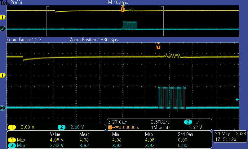
    I finally found what was causing the issue. I understood after I had a look with an oscilloscope, here is the MISO/POCI (line 1) with the Clock (line 2). Clearly something was preventing the PGA from pulling the line to a low level, and that made me think that maybe the connection was blocked by something on the EVM board.

    The issue was coming from a component used with the OWI on the EVM, the TS5A23159. On my setup I plugged the Master Cable's pins in the connector of the USB2ANY board, because it was easier to do it this way compared to connecting the pins to the testing points on the EVM. The mistake is that the MISO and MOSI pins on the USB2ANY connector go through the TS5A23159 before going to the PGA socket. But without the USB2ANY board, the TS5A23159 was not powered (it is powered by an external source and NOT by the EVM's regulators, and I missed that detail when I checked the EVM's electrical schematics). When I connected the VCC pin from my Master cable to the 5V_EXT pin of the USB2ANY connector to power this component, the SPI communications finally worked as intended.

    Turns out it was just an hardware issue I made because of my setup. Thanks again for your patience and your help.

    Best,

    Benjamin.