This thread has been locked.

If you have a related question, please click the "Ask a related question" button in the top right corner. The newly created question will be automatically linked to this question.

IWR6843ISK: RX Gain

Part Number: IWR6843ISK
Other Parts Discussed in Thread: DCA1000EVM

First I use mmwave studio 2.1.1.0 to capture raw data from DCA1000 and IWR6843IWK

Here is my lofgile

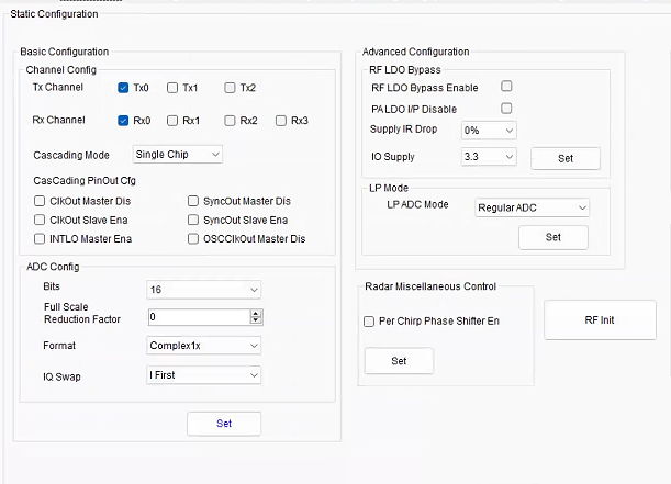
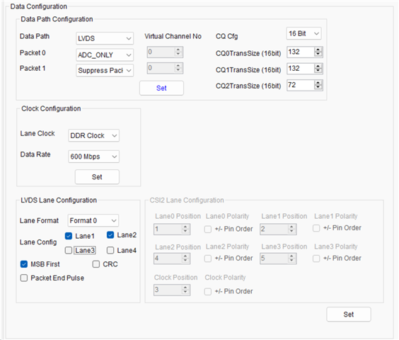
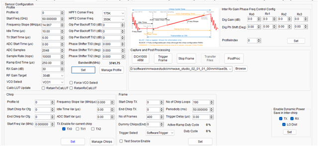
13-May-2023 12:48:46: API:select_capture_device,DCA1000,0,
13-May-2023 12:49:13: API:select_chip_version,IWR6843,0,
13-May-2023 12:50:28: API:select_chip_version,IWR6843,0,
13-May-2023 12:50:40: API:ChannelConfig,1,1,0,
13-May-2023 12:50:40: API:AdcOutConfig,2,1,0,
13-May-2023 12:50:41: API:DataFmtConfig,1,2,1,0,1,0,
13-May-2023 12:50:43: API:LowPowerConfig,0,0,0,
13-May-2023 12:50:47: API:DataPathConfig,1,1,0,2,0,
13-May-2023 12:50:48: API:LvdsClkConfig,1,1,0,
13-May-2023 12:50:48: TSW1400 Sampling rate : 600000000 7500000,0,
13-May-2023 12:50:48: API:SetHsiClock,9,0,
13-May-2023 12:50:51: API:LaneConfig,3,0,
13-May-2023 12:50:51: API:LvdsLaneConfig,0,1,0,
13-May-2023 12:51:06: API:ProfileConfig,0,1491308089,1000,600,25000,0,0,414,0,2048,10000,0,0,30,0,
13-May-2023 12:51:07: API:ChirpConfig,0,0,0,0,0,0,0,1,0,
13-May-2023 12:51:14: API:EnableTestSource,0,1,0,
13-May-2023 12:51:14: API:FrameConfig,0,0,400,190,10000000,0,4096,0,
13-May-2023 12:51:14: API:AdvancedFrameConfig,1,0,0,0,1,190,10000000,0,1,1,10000000,0,0,0,0,0,0,0,0,0,0,0,0,0,0,0,0,0,0,0,0,0,0,0,0,0,0,0,400,0,0,0,0,0,0,0,0,0,0,0,0,0,0,0,0,
13-May-2023 12:51:15: API:select_capture_device,DCA1000,0,
13-May-2023 12:56:53: API:SensorStart,0,
13-May-2023 12:57:42: API:update_num_adc_files_and_frames,1,400,1,0,
13-May-2023 13:01:40: API:SensorStart,0,
13-May-2023 13:02:18: API:update_num_adc_files_and_frames,1,400,1,0,
13-May-2023 13:04:33: API:SensorStart,0,

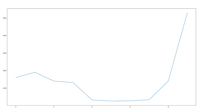
And I get this range profile(subject is about 40cm away from radar)

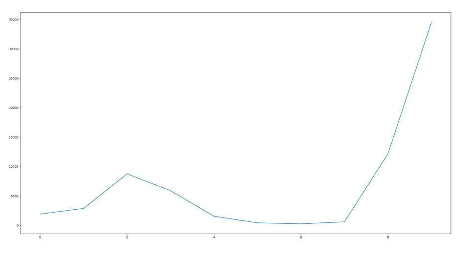
It can be seen that the amplitude of subject is about 35000

After that,I call  DCA1000EVM_CLI_Control.exe and sent config file as below to capture raw data

dfeDataOutputMode 1
channelCfg 1 1 0
adcCfg 2 1
adcbufCfg -1 0 1 1 1
profileCfg 0 60.1 10 6 250 10 0 14.991 0 2048 10000 0 0 30
chirpCfg 0 0 0 0 0 0 0 1
frameCfg 0 0 190 0 50 1 0
lowPower 0 0
lvdsStreamCfg -1 0 1 0
calibMonCfg 1 1
monCalibReportCfg 1 1 0
txPowerMonCfg 1 0 0
txPowerMonCfg 1 1 0
txPowerMonCfg 1 2 0
txBallbreakMonCfg 1 0
txBallbreakMonCfg 1 1
txBallbreakMonCfg 1 2
rxGainPhaseMonCfg 1 0
tempMonCfg 1 20
synthFreqMonCfg 1 0
pllConVoltMonCfg 1
dualClkCompMonCfg 1
rxIfStageMonCfg 1 0
extAnaSigMonCfg 0
pmClkSigMonCfg 1 0
rxIntAnaSigMonCfg 1 0
gpadcSigMonCfg 1

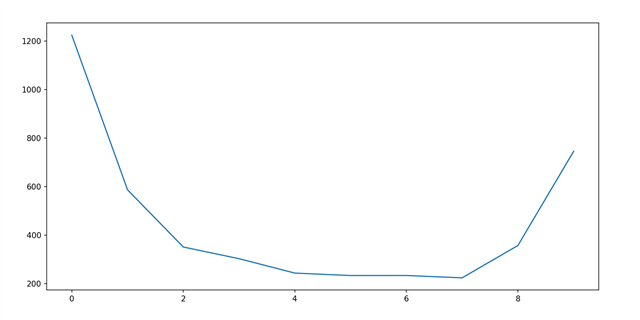
And I get  this range _profle in the same scenario

 the amplitude of subject is under 1000 ,it's much smaller than 35000(the former),  introduce a huge noise figure.

 Both the experiment have the same Rx gain(30db) and  other parameters,What drives the differences?

I try to achieve the same SNR as the former,how should I modify my config file ?

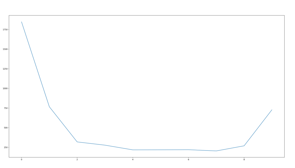
I also try to modify Rx gain to 48,the maxinum according to table5.23 in C:\ti\mmwave_dfp_01_02_06_03\docs\mmWave-Radar-Interface-Control.pdf.

The amplitude is higher than 1000 but still much smaller than 35000.

  • Hi, 

    We are working on an answer to this now, Thank you for your patience.

    Best,

    Nate

  • HI,  there:

    Please send me thconfiguration through the GUI capture.  So, it will be easier to compare it with the CLI configuration. 

    Best,

    Zigang

  • Hi,

    this is my configuration of mmwave_studio.

    Thanks for your reply.

  • HI, there:

    Your OOB demo configuration was using 10dB backoff on TX1, and there are several other setting that are slightly different.  Please try 

    profileCfg 0 60.0 10 6 250 0 0 14.967 0 2048 10000 0 0 30

    Best,

    Zigang

  • Hi,

    Thanks for your reply.

    I tried this new config file .

    dfeDataOutputMode 1
    channelCfg 1 1 0
    adcCfg 2 1
    adcbufCfg -1 0 1 1 1
    profileCfg 0 60.0 10 6 250 0 0 14.967 0 2048 10000 0 0 30
    chirpCfg 0 0 0 0 0 0 0 1
    frameCfg 0 0 190 0 50 1 0
    lowPower 0 0
    lvdsStreamCfg -1 0 1 0
    calibMonCfg 1 1
    monCalibReportCfg 1 1 0
    txPowerMonCfg 1 0 0
    txPowerMonCfg 1 1 0
    txPowerMonCfg 1 2 0
    txBallbreakMonCfg 1 0
    txBallbreakMonCfg 1 1
    txBallbreakMonCfg 1 2
    rxGainPhaseMonCfg 1 0
    tempMonCfg 1 20
    synthFreqMonCfg 1 0
    pllConVoltMonCfg 1
    dualClkCompMonCfg 1
    rxIfStageMonCfg 1 0
    extAnaSigMonCfg 0
    pmClkSigMonCfg 1 0
    rxIntAnaSigMonCfg 1 0
    gpadcSigMonCfg 1

    But the results are similiar to before ,things didn't get better.

  • HI, 

    So the scale may be different between the two applications.  But why the shape is also different? Do you have any ideas?  Are these figures generated from the tools? or by you?

    Best,

    Zigang

  • Hi,

    Thanks for your reply.

    The two experiments were performed in the same scenario.I haved tried many times but  result is the same.

    This is my test scenario and The radar didn't move.

  • Hi,

    These images are generated from same python files and are the result of a 1D Fourier transform of raw_data

  • I see, so you are the one created the python file.   In that case, you need to understand the data format between RAW data from radar studio and from OOB demo are different.   

    For radar studio, the data is I before Q, and I1, I2, Q1, Q2, I3, I4, Q3, Q4, ...

    For OOB demo, the data is Q before I, and usually is Q1, I1, Q2, I2, ...

    You can send me the json file that you used doing OOB demo data capture to confirm. 

    Best,

    Zigang

  • Oh!

    Thanks for your reply.

    I modified my python file and problem was solved.Thanks a lot.

    Regards.

  • Hi,

    This is my  json file.

    Does it mean  Q1, I1, Q2, I2, ...?

    {
      "DCA1000Config": {
        "dataLoggingMode": "raw",
        "dataTransferMode": "LVDSCapture",
        "dataCaptureMode": "ethernetStream",
        "lvdsMode": 2,
        "dataFormatMode": 3,
        "packetDelay_us": 25,
        "ethernetConfig": {
          "DCA1000IPAddress": "192.168.33.180",
          "DCA1000ConfigPort": 4096,
          "DCA1000DataPort": 4098
        },
        "ethernetConfigUpdate": {
          "systemIPAddress": "192.168.33.30",
          "DCA1000IPAddress": "192.168.33.180",
          "DCA1000MACAddress": "12.34.56.78.90.12",
          "DCA1000ConfigPort": 4096,
          "DCA1000DataPort": 4098
        },
        "captureConfig": {
    	  "fileBasePath": "F:\\raw_data",
          "filePrefix": "adc_data",
          "maxRecFileSize_MB": 1024,
          "sequenceNumberEnable": 1,
          "captureStopMode": "duration",
          "bytesToCapture": 4000,
          "durationToCapture_ms": 21000,
          "framesToCapture": 400
        },
        "dataFormatConfig": {
          "MSBToggle": 0,
          "laneFmtMap": 0,
          "reorderEnable": 0,
          "dataPortConfig": [
            {
              "portIdx": 0,
              "dataType": "real"
            },
            {
              "portIdx": 1,
              "dataType": "complex"
            },
            {
              "portIdx": 2,
              "dataType": "real"
            },
            {
              "portIdx": 3,
              "dataType": "real"
            },
            {
              "portIdx": 4,
              "dataType": "complex"
            }
          ]
        }
      }
    }

  • Hi, there:

    You need to check the setting of "reorderEnable" in json file. And you need to know in ADC data the order of I sample and Q sample.  

    Let me give an example,

    1) in OOB demo Q sample is first, and if "reorderEnable" = 1, then the data order is

    Q1, I1, Q2, I2, and etc

    1) in OOB demo Q sample is first, and if "reorderEnable" = 0, then the data order is

    Q1, Q2, I1, I2, and etc

    Best,

    Zigang

  • Hi,

    Thanks for your reply.

    I see, but how to determine the order of I sample and Q sample

  • You can search inside the SDK users guide.   Search adcbufCfg, you can find that Q sample first is the only mode that supported by SDK OOB demo.

    In radar studio, you have option, but by default, it is I first.  Check your figure below.

    Best,

    Zigang