This thread has been locked.

If you have a related question, please click the "Ask a related question" button in the top right corner. The newly created question will be automatically linked to this question.

TDC1000: TDC1000 cannot extend the detection window through the value of T0

Part Number: TDC1000
Other Parts Discussed in Thread: TDC7200

Hi,

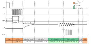
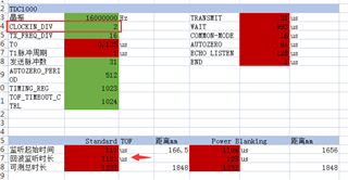
      My clock is 16Mhz,Using mode 0,The frequency of the transducer is 1Mhz,Standard TOF Measurement。

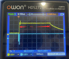
      I want to measure the flow rate through TDC1000. The distance between the two transceivers is 1.73 meters, and the flight time of 1.73 meters is around 1200us. However, I now configure the monitoring window through registers, and the maximum length is only around 700us no matter how it is configured. Through observation, I found that the register configuration of T0 remains basically unchanged regardless of configuration 1 or 2.

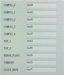
    The following is a waveform diagram of my TDC1000 register configuration and the detection window for the farthest 700us.

    According to the logic, the configuration of this register can measure a time of around 1200us?

  • Hello Chao,

    Thanks for posting to the sensing forum!

    I first wanted to mention that TDC1000 is no longer recommended for flow meters due to its low accuracy. The recommended device for flow metering is the MSP430430FR6043.

    I found that the register configuration of T0 remains basically unchanged regardless of configuration 1 or 2

    I am not sure what you meant by this comment above, but T0 heavily impacts the time allotted by your listening window. Using a 16MHz clock will decrease the amount of total time available for you to make a measurement. There are a couple of options you can divide your 16MHz input clock internally using the CLOCKIN_DIV settings found in the CLOCK_RATE register to 8MHz almost doubling the time available in the listening window. The other options would be to change the input clock to something lower to generate the length that you require.

    The length of the window can be calculated by adding the length of all of these values here starting from COMMON_MODE all the way to ECHO LISTEN. The comparator only activates during the WAIT/ECHO LISTEN periods. In reality with the 16MHz clock your max listening window is only ~560us long with a 8MHz clock then you can increase that to about 1120us. 

    An issue I also noted with your configuration is that your using a 16MHz input clock but need to transmit at 1MHz but your TX clock division is set to 8 meaning that you will generate a 2MHz signal. To generate the 1MHz pulse you need to update the CONFIG_0 register to divide by 16.

    I hope this helps!

    Best,

    Isaac

  • Hi,Isaac


    An issue I also noted with your configuration is that your using a 16MHz input clock but need to transmit at 1MHz but your TX clock division is set to 8 meaning that you will generate a 2MHz signal. To generate the 1MHz pulse you need to update the CONFIG_0 register to divide by 16.

    CONFIG_0 The screenshot I took is incorrect and should be set to 7F.

    In reality with the 16MHz clock your max listening window is only ~560us long

    Calculated through the TDC1000 datasheet, using a 16Mhz clock, CLOCKIN_ If DIV is set to 2, the window time that can be monitored is 1121us instead of 560us.

    The datasheet also states that the measurement range is 8ms. How can I achieve such a large measurement range?

  • Hello Chao,

    Good to know the screenshot was incorrect. I just wanted to make sure your configuration was correct.

    Calculated through the TDC1000 datasheet, using a 16Mhz clock, CLOCKIN_ If DIV is set to 2, the window time that can be monitored is 1121us instead of 560us.

    That's correct, as mentioned you can use the internal clock divider (CLOCKIN_DIV) to divide your 16MHz clock by 2 to generate the 8MHz clock and get a 1121us listening window.

    The datasheet also states that the measurement range is 8ms. How can I achieve such a large measurement range?

    To get a larger measurement range you would need to slow down your clock. For example you could use a 2MHz clock divided by 2 with the max values on the TIMING_REG in order to achieve a 8ms listening window. Although you would not require such a high value on your listening window for water couple applications since high frequencies dont carry as much energy as lower ultrasonic frequencies (for example 40kHz) so they attenuate faster, so unless the transducer is excited with a really large voltage the signal would not last up to 8ms. These configurations are mostly there for low frequency air coupled applications where the speed of sound is much lower.

    I hope this helps!

    Best,

    Isaac

  • Hi,Isaac

       We have already solved this problem. The TDC1000 has a continuous RX listening mode, which can be turned off by registering the echo timeout. In the absence of echoes, we cooperate with TDC7200 to clear the timeout flag bit and write the ERROR register of TDC1000 to terminate this test when the TDC7200 timer times out.  

  • Hello Chao,

    That works too! Glad to hear you were able to find a workaround. Let me know if there are any other questions I can help out with.

    Best,

    Isaac