Hi TI expert,
I have one question regarding the guard area while designing IWR6843AOP. Please see below picture.
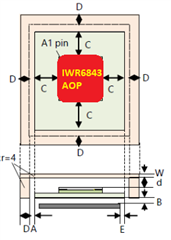
Is there any guard or keep-out area requirement for IWR6843AOP? We can calculate the air cap between the top housing and the radar module following TI's radome application note in "mmWave Radar Radome Design Guide". But how about the distance between the PCB edge and the radar AOP module? Like below picture the "C" and "D" distances, do you have suggestion?
The green color is PCB area, and the pink color is the radome area.