This thread has been locked.

If you have a related question, please click the "Ask a related question" button in the top right corner. The newly created question will be automatically linked to this question.

TDC1000-C2000EVM: Help with configuring the evaluation board.

Part Number: TDC1000-C2000EVM
Other Parts Discussed in Thread: TDC1000

Hi,

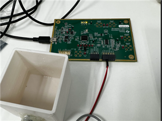
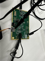
I recently purchased the TDC1000-C2000EVM along with a 1Mhz transducer (This is a metal enclosed one). 

My purpose is to use it as a fluid identification device which measure the liquids speed of sound from a fixed distance.

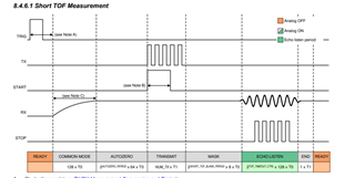
From the GUI User guide I am unable to figure out what settings I need to change to get the board to output the correct ToF value.

I have a liquid with the speed of sound of 1500m/s (Water) and another with 1200m/s. 

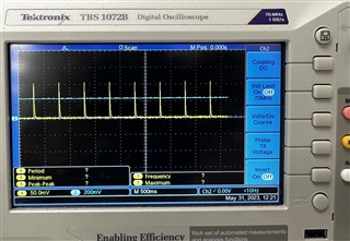
My distance is 6cm (so 12cm for sound to reflect back). meaning my ToF shoud be 80us and 100us. However my reading output is currently 30us

What configuartion value do i use in the gui and how do i figure out which one i need? Is there a detailed datasheet?

My Setup. The sensor is touching the liquid (the liquid not shown in this image for clarity)

  • Hello Divraj,

    Thanks for posting to the sensors forum!

    The TDC1000 has a configurable echo listening window, where the devices internal comparator will enable and generate STOP pulses. My assumption is that perhaps you have the listening window enabled too early so it is triggering off of the excitation voltage to the transducer. I assume you may be using the Short TOF measurement since the distance is kind of small, so the main values to pay attention to would be SHORT_TOF_BLANK_PERIOD and the TOF_TIMEOUT_CTRL. Please refer to image below for measurement sequence and timing.

    The TDC1000 datasheet can be found at this link: https://www.ti.com/lit/ds/symlink/tdc1000.pdf

    For other documentation on the TDC1000 please look at the devices product page on TI.com: https://www.ti.com/product/TDC1000

    Best,

    Isaac

  • Thanks for that working. Im trying to setup the oscillascope with the GUI. However Im unable to see any waveform on my oscillascope. I have turned on the continuous trigger as the user guide suggest. I have attached probes on the start and comp buffer however not seeing anything. Any thing Im missing?

  • Hello Divraj,

    Good to hear that you were able to get something working! I typically recommend setting up the device to do a single measurement (one shot) to help setup the scope. Since it can be hard I typically probe the TX, START, and STOP signals. Once I am able to locate the START and STOP signals then I add the COMP buffer. But usually the one shot will help since I know when the scope should be triggering everytime I click the measurement button.

    Best,

    Isaac

  • I just cant seem to figure it out. Probe 1 (yellow) is connected to the TX pin directly (i.e. the Positive for the transducer). and Probe 2 is connected to the comp pin. 

    TX1 just has a spike (running continous to free up my hands). and COMP is just gives is a constant 200mV reading. See images

  • Hello Divraj,

    It looks like you may be too zoomed out to see the data on the COMPIN line. You need to zoom in on the TX pulse and when you have an echo you should be able to see it during the listening window like the image below.

    One thing I noticed on your capture is that the voltages don't look correct on your scope. Vref on your COMPIN signal should be around 2.5V and TX pulses should be around 4V. I would check your probes/scope to make sure you don't have any issues there. 

    Best,

    Isaac

  • Can you provide your Config settings. Because even on my TX pin im getting nowhere near 2V. (all under 0.5V). My oscillascope is working, after testing with different circuit. Im running firmware 1.42, Is it possible that is turned off in any way?

  • Hello Divraj,

    On the EVM the voltage is fixed since it uses USB VBUS to power the device. There aren't any configurations in the GUI or in the device that will alter this voltage, it would have to be changed in hardware.

    You can confirm if the voltage going to your device is in reality near 5V, you can check TP17 DUT_VDD, if you probe this pin you can identify what we are powering the device with. Perhaps use a scope and a multimeter to check this pin just in case there is some attenuation happening in your probes. Based on your capture above, it looks like the device is on an producing what its configured to when in continuous mode but the voltages look incorrect/ too small. So I think checking the voltage on the device is probably the first step here.

    But here is my configuration if needed: 

    CONFIG0:0x45

    CONFIG1:0x41

    CONFIG2:0x00

    CONFIG3:0x0C

    CONFIG4:0x5F

    TOF0: 0X1E

    TOF1: 0x40

    TIMEOUT:0x23

    CLOCK_RATE:0x01

    Version 1.42 of the firmware is the latest version of the firmware.

    I hope this helps!

    Best,

    Isaac