A related question is a question created from another question. When the related question is created, it will be automatically linked to the original question.
If you have a related question, please click the "Ask a related question" button in the top right corner. The newly created question will be automatically linked to this question.
We are working on AWR6843, there is no issue in particular. We want to know whether the standard units for ADC samples is volts or millivolts ? similarly would want to understand the standard units for Range FFT data.
The Range FFT samples are based off the RF ADC step sizes. Can you perhaps tell us why you're interested in the units here? They shouldn't really be needed as the radar measurements are almost always relative to themselves/the noise floor.
The idea here is to understand the relationship between the radar antenna measurements and the ADC value.
For example any sensor would measure the psychical parameter (here the wave power) in-terms of voltage. This voltage is converted by ADC into 16bit integer. We would like to understand the physics or the relation between the reflected wave power and the ADC value(or the voltage value at least).
The major reason that we ass this is to convince our Tier 1 customer that the environment response that we are seeing in our setup is an expected performance of the radar technology itself and also to show them we have a clear understanding of these concepts.
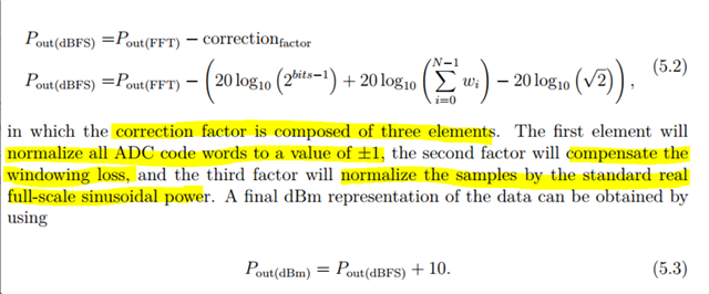
I understand that the values are usually in dBFS.but without the correction factor mentions in that thread, the value doesn't become relative and cannot be represented as dBFS. Additionally the Pout value mentioned has already undergone a log conversion. Our request is about the unit before the log conversion.
I would like to redirect you to my comment above rather than the question here, which explains our need for the actual physical unit or the relation to the received antenna power, rather than the relative unit. Any help on this would be really appreciated.
We know this and we are not asking for this explanation.
Let me repeat my question.
We want to know the relation between the reflected wave power at the antenna input and the mV that is fed to the ADC input.
We do not want to know how to calculate dBFS. We do not want to know how ADC bit values are represented in dB or dBFS. We don't want to calculate the relative power. We do not want the relation to mV at antenna lines but at ADC input (after LNA, adaptive gain & mixers).
Below is an example calculation to get the amplitude level at the LNA input -> If you are using 12bit ADC mode , a value of 0x7FF corresponds to positive peak value at the ADC input, which corresponds to 1V peak voltage at the ADC input. 1V peak corresponds to 10dBm power (50 ohms system , assuming sinusoidal signal). Now if the RX gain setting is 30dB , this means at the LNA input the power level is (10dbm -30dbm ) = -20dBm.
This way you can back calculate the LNA input for any corresponding ADC code word .