This thread has been locked.

If you have a related question, please click the "Ask a related question" button in the top right corner. The newly created question will be automatically linked to this question.

TUSS4440: Configure clock in IOMode0

Part Number: TUSS4440

Hi Team,

We would like to ask your help regarding our customer's inquiry below.

I have built a prototype using TUSS4440 . Am trying to configure the configure a clock of 40KHz in IOMode0 . I am unable to see anything at IO1 & IO2.

We have built a prototype board using TUSS4440 and using external ST Microcontroller Evaluation board for Programming.

Using this interface reading and writing of the Registers are being done properly with the SPI Mode 2.

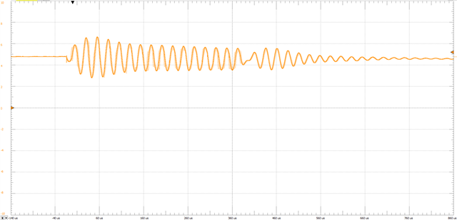
Provided the Burst pulses of 8 every second at IO2 pin. There weren't any pulses generated at the pins OUTA, OUTB.

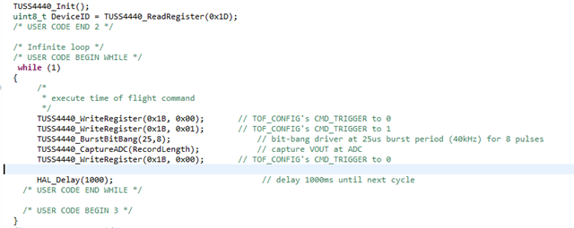
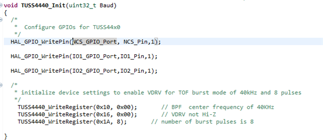
Attaching the firmware for reference. 

Regards,

Danilo

  • Hello Danilo,

    Thanks for posting to the sensors forum!

    Can the customer provide a scope capture for the IO2 pin? Have they performed a read of the DEV_STAT register to see if the device reports a any issues after trying to drive the device?

    Best,

    Isaac

  • Hi Isaac,

    Thank you for your response. Please see the feedback of our customer below.

    The DEV_STAT is read as 0 after driving the device by giving the pulses at IO2.
    Attaching the visual at IO2.

    Regards,

    Danilo

  • Hello Danilo,

    Thank you for the information. Can the customer probe the OUTA and OUTB pins while they try excite the TUSS4440 device on their board along with the IO2 signal?

    Have they tried using a different IO_MODE to see if perhaps they are not sending the CMD_TRIGGER  appropriately. If they have access to the IO1 signal they may be able to check this.

    Could they also provide schematics for their board?

    Best,

    Isaac

  • Hi Isaac,

    Please see this update from our customer.

    Apologies for the late reply , We tried a different IO_MODE by exciting both IO1 & IO2. There's no change in the OUTA & OUTB.
    Unfortunately i could not capture all the waveforms .Attaching the Schematics for reference.

    TUSS4440-2.pdf

    Regards,

    Danilo

  • Hello Danilo,

    We are currently out of office due to a holiday but I will review your reply tomorrow when we have returned. Thanks!

    Best,

    Isaac

  • Hello Danilo,

    I reviewed their schematic and I don't see anything majorly wrong with it, in fact it looks very similar to the TUSS4440EVM which I am able to get a signal out of the OUTA and OUTB pins that looks like this image below:

    My only comment would be on the VDRV capacitor, I would recommend using a larger capacitor currently they have a 0.1uF while the EVM uses 2.2uF. Does the customer happen to have a BOOSTXL-TUSS4440EVM? My concern is that perhaps they are not communicating with the device properly hence why they dont see any signals being generated by the device.

    Best

    Isaac