As a quick note to other engineers, don't bother with the TI chat, you will get redirected here after several hours, adding a day to your problem solving. Far better just to post here on E2E and get engineering input directly.
Back to the issue:
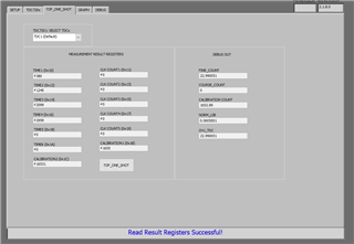
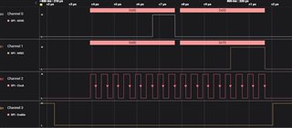
I have a TDC7201 on a custom board, using 10 MHz LVCMOS reference clock, with a 100 ns duration 1Hz pulse as start signal to TDC1 and a 20 MHz LVCMOS clock as the stop signal. TDC2 is disconnected. I will admit to having some issues getting repeated readings from registers (after a short while, previously successful register readings return 0x0) but I cycle the enable pin between measurements (and reconfiguration) which has solved this in the immediate term. I have managed to get to the point where I can initiate a new measurement in Mode 1 (start->stop is well under 2000 ns), detect the hardware interrupt and read the TIMEn and CALIBRATION1 and CALIBRATION2 registers, as well as writing to the INT_STATUS registers to reset the interrupt bits.
My main issue at this stage is that when I calculate the normLSB, it is returning values around 14300 picoseconds, or 14 nanoseconds, which is extremely poor resolution compared to the spec sheet potential of the IC. For example, typical CALIBRATION1 value is 7 and typical CALBRATION2 value is 8B when CONFIG1 register is set for 20 calibration clock periods. From this I calculate calCount ~6.95 and then using my 10 MHz reference clock this leads me to normLSB ~14300 ps.
Hardware config is as shown. VDD is 3.3V, as are the enable, SPI, start, stop and reference clock signals.