This thread has been locked.

If you have a related question, please click the "Ask a related question" button in the top right corner. The newly created question will be automatically linked to this question.

LDC0851: Using wirewound coils

Part Number: LDC0851

Hi TI,

I'm working on a proximity sensor with the LDC0851 in a very small device and am looking to detect a metal object passing by at about 20mm from the sensor.  We are in an early design stage and there are two design paths for the coil:

1. keep the coil within a 10x10mm surface envelope

2. enlarge the coil to a max 40x40mm surface - however, in this scenario there would be two permanent magnets overlapping with the coil surface

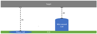
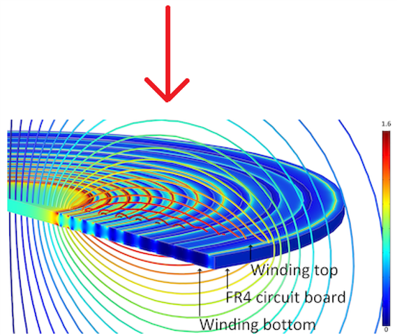
Since d_switch would be  3,75mm with a PCB coil of 10x10mm and ADJ of 1 (equation 1: par. 8.3.3 in the datasheet) that is not going to suffice. Therefore I am interested in knowing what the design steps would be for a wirewound coil; would that enable me to increase the available inductance within the limited envelope of path 1?

Alternatively, in path 2 the max sensing distance according to Eq. 1 would be 15mm. In that case, we can again consider a wirewound coil, but then I'd be interested in how the permanent magnets would affect the field. Could this be mitigated with ferrite shielding for example?

Thanks in advance!

  • Hello, 

    The sensing distance of the LDC0851 is primarily determined by the coil diameter. Increasing the inductance alone would not improve your sensing distance. The wirewound would only help if the face of the sensor moves closer to the target you are trying to sense. 

    For the impact of the magnets, the DC magnetic field of the magnets will not have any impact, but the surface of the magnets may allow for eddy currents to form which will act as a normal metal target for the LDC0851. Using a ferrite sheet can help shield from this impact but you would also be partially shielding your target if the magnet is in between the sensor and your target. 

    Best Regards, 

    Justin Beigel

  • Hi Justin,

    Thanks for your response! Generally, I understand what you are saying, however:

    The wirewound would only help if the face of the sensor moves closer to the target you are trying to sense. 

    I am not clear what you mean with this. Do you mean that wirewound inductors would only work at a short distance, or when a target perpendicularly approaches the sensor?

    Our target will move laterally past the sensor at a height variable between 20 - 10 mm (as crudely depicted below). Would you recommend a circular PCB coil then? I thought a wirewound coil would have the added benefit of a larger amount of windings at a larger diameter (not coiling inwards as much as a PCB coil) - and thus a larger sensing distance. OR would a racetrack or other shape have a benefit in this situation?

    And the magnets are located on the other side of the coil (i.e. 'underneath' the coil - if the target moves 'above' the coil) - so I suppose the ferrite would not interfere as much with target detection.

    Thanks again!

  • Hello, 

    What I mean is, if your wire wound coil sticks up from the PCB, it reduces the sensing distance between the coils and the target compared to a planar coil: 

    However, if this is not the case then the diameter of the coil is the main factor to increase the sensing distance. 

    And since the magnets are below the coil, shielding and increasing the sensor size may be best. One factor to consider is the size of your target in relation to your sensor coils. This E2E post has more information on the impact of different target sizes. If your target is still around the size of your 40mm coil or larger, then there shouldn't be any issues. 

    Best Regards, 

    Justin Beigel

  • Hi Justin,

    I understand what you mean now, thanks for the clarification.

    We're in a bit of a tough design space though, as we are trying to detect a small metallic ring (OD 11mm, ID 10mm, h 4mm) at a distance in the range of 15 +/- 5mm (measured from the PCB; any components with z-height should protrude downwards). That's why I'm trying to understand what other parameters there are to optimize our sensing distance. Is the number of windings in no way a factor for this?

    In addition, where over the (spiral) coil is the sensing distance the furthest? Would that be right between the ID and OD of the windings (i.e. at the red arrow as drawn below)? Are there different topologies of coils that we should consider for further sensing?

    Best regards,

    Tal Amram

  • Hello, 

    For a ring, I think it is best to stick with a circular sensor coil. One issue with using a ring shape as the metal target is that the coupling between the sensor coils and metal are less than a uniform target. Similar to how the target size matters, the hole in the center can lead to less change in inductance. The best placement is to center your target over the center of the coil. 

    The inner most windings contribute very little to the magnetic field generated by the sensor coil which is why the number of windings does not have a significant impact on sensing distance. The outer diameter is really the only thing that makes a significant change in the sensing distance. 

    Best Regards, 

    Justin Beigel

  • Ok, I think we will go forward with a few coil designs and do some trials to see how far we can stretch it. Thanks for your thoughts on this!

  • Sounds good. Let us know if you have any other questions. 

    Best Regards, 

    Justin Beigel