This thread has been locked.

If you have a related question, please click the "Ask a related question" button in the top right corner. The newly created question will be automatically linked to this question.

IWRL6432BOOST: Enabling data streaming via LDVS in software

Part Number: IWRL6432BOOST
Other Parts Discussed in Thread: IWRL6432, DCA1000EVM

I have been trying to get the IWRL6432 to stream radar ADC data to the DCA1000 from startup, without the radar EVM having to be configured via SPI. 

I have made the following changes to the motion and presence detector demo code to try and get this working:

  • Enabled CLI bypass in mmw_cli.c, and set adcLogging to 1
  • Updated the function Mmwave_populateDefaultOpenCfg in common_full.c to replicate the settings with which we have successfully captured data using mmWaveStudio:
    • Enable lane rate update
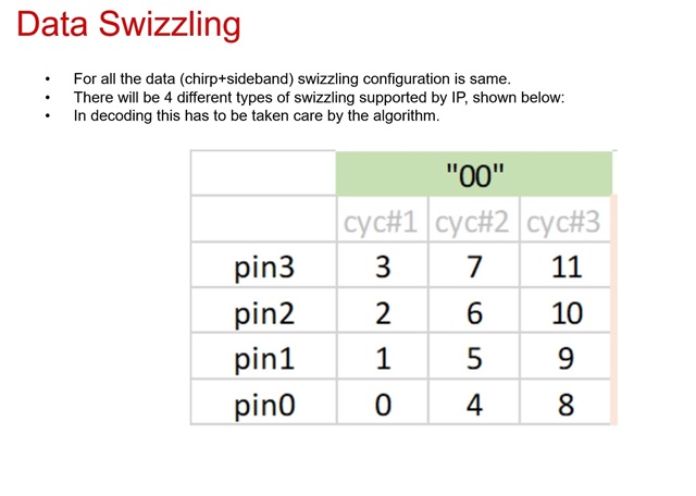
    • Data swizzling mode Pin 0, bit 0, cycle 3

 I've got this code in Mmwave_populateDefaultOpenCfg:

        ptrOpenCfg->fecRDIFCtrlCmd.c_RdifCfg = (M_RL_API_CTRL_ON << M_RL_FECSS_RDIF_LANE_RATE_UPDATE)
            | (M_RL_FECSS_RDIF_SWIZZL_PIN0_BIT0_CYL3 << M_RL_FECSS_RDIF_SWIZZL_MODE);

Using this configuration, with the test pattern disabled, I am not measuring any activity on the RADAR_LVDS_CLK line on the EVM.

However, if I change the code to enable the test pattern, I do see this clock line running.

ptrOpenCfg->fecRDIFCtrlCmd.c_TestPatternEn = M_RL_FECSS_TEST_PATRN_ENA;

I can't quite figure out where in the code the test pattern setting is applied so that the device sends the test pattern, or where in the code the real sampled ADC data would be sent out.

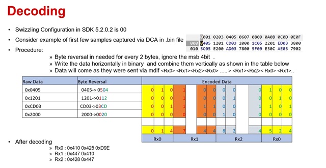
I am using version 5.02.00.02 if the SDK, and have tried configuring the switches on the BOOST board for both functional mode and debug using mmWaveStudio.

Can you perhaps give me some guidance as to how I can get the EVM to stream out the radar data?

  • Hi,

    SDK 5.2 supports streaming the adc data out of the device

    You need to set the below configurations in the cfg file

    adcLogging 1
    lowPowerCfg 0

    Low power mode needs to be disabled. ADC data is sent along with the sideband data. If you are capturing with DCA1000, sideband data will help you align the chirp data correctly as DCA1000 appends few bytes of junk data in some cases

    Regards,

    Abhishek

  • Hi Abishek,

    Thanks, when I disabled lower power and enabled the sideband data, I could see the LVDS clock running without having to enable the test pattern.

    However, when I connect a DCA1000 and try to start a capture, I get a message saying "No LVDS data" after about 30 seconds.

    I am using the following commands to start a capture:

    DCA1000EVM_CLI_Control fpga "Config.json"
    DCA1000EVM_CLI_Control eeprom "Config.json"
    DCA1000EVM_CLI_Control record "Config.json"
    DCA1000EVM_CLI_Record -c "Config.json"
    My config JSON file is based on the example in the DCA1000EVM CLI Software User Guide.
    Can you perhaps tell me what I need to check to ensure that the EVM, DCA board, capture commands and JSON file are correct?
    Also, is there currently no way to capture data in lower power mode? Or is it planned to support this in the future?
    Thanks very much,
    Bertus
  • Hi Bertus,

    You can start the demo and send the config commands through the visualizer and then send the DCA1000 CLI commands

    You can use the "captureStopMode": "bytes", and configure the required number of bytes in the json file

    You can use the below steps

    DCA1000EVM_CLI_Control fpga "Config.json"
    DCA1000EVM_CLI_Control eeprom "Config.json"
    DCA1000EVM_CLI_Control record "Config.json"
    DCA1000EVM_CLI_Control start_record "Config.json"
    Do note that switch settings on the EVM should be same as mentioned in the visualizer after the successful flashing (Flash tab)
    There is no plan to support the LVDS data capture in low power mode as it is only a debug interface
    Regards,
    Abhishek


  • Hi Abishek,

    Thanks, I managed to get it working by ensuring that the switches on the DCA1000 and the settings in Config.json are all consistent with the EVM firmware. It just took some time for me to understand all the settings.

    I am now able to capture a file, though it looks if I am not correctly identifying the start of a frame when processing it. I am still debugging that, but if you could give me an idea of how to identify the start of a frame, that would be great.

    I'll call this issue resolved for now, and create another one if I can't figure out how to interpret the data correctly.

    Thanks very much for the help,

    Bertus

  • Hi Bertus,

    Were you able to decode the packets? You need to first check for the sideband data 

    Once the side band data is found to be correct then you can extract the chirp data

    If you find that sideband data is split, try  to capture with another windows machine. Sometimes the ethernet driver of the PC splits the packet such that sideband dats is broken

    Regards,

    Abhishek

  • Hi Abishek,

    I haven't been able to decode the packets yet. Can you perhaps give me some guidance on how to identify the sideband data?

    Thanks,

    Bertus

  • Hi Bertus,

    We have a r script which decodes the data collected in DCA1000 while running the SDK 5.2. The script takes the .cfg file as the input along with the log collected in DCA1000. The script allows you to select the frame/burst/chirp and displays the data for the selected chirp

    #MDIF Chirp data and sideband data
    #!/usr/bin/env Rscript

    rm(list = ls())
    folder_name = "C:/d_drive/lpradar/mdif/mdif_data_decoder_sdk_5_2/"
    t<-readLines(paste0(folder_name,"MotionDetect_mdif.cfg"), n=12)

    N_samples = as.integer(strsplit(t[9], split = " ")[[1]][5])
    N_chirps =as.integer(strsplit(t[11], split = " ")[[1]][2])
    N_brusts=as.integer(strsplit(t[11], split = " ")[[1]][5])
    N_frames=as.integer(strsplit(t[11], split = " ")[[1]][7])

    N_rx = 3
    max_frame=128
    side_band_EN=1
    if (N_frames)
    {
    N_frames=N_frames
    } else {N_frames = max_frame}

    chirp1=N_chirps*N_brusts
    chirps=N_frames*N_chirps*N_brusts
    total_samples_per_rx = N_samples * chirps

    N_bits = 12

    total_samples = total_samples_per_rx * N_rx
    total_samples_per_chrip = N_samples * N_rx
    x=as.integer(total_samples/728)

    #input <- readBin(paste0(folder_name,"mdif_capture_25_Raw_0.bin"), what = integer(), n = total_samples + 3*x+3, size = 2)
    input <- readBin(paste0(folder_name,"mdif_capture_sdk_5_2_Raw_0.bin"), what = integer(), n = total_samples + 3*x+3, size = 2)

    input = input[4:(total_samples +3*x +3)]
    input3 = array(0,total_samples)
    for (m in 1:x)
    {
    input3[(1+728*(m-1)):(728*m)]= input[(1+(731*(m-1))):((731*m)-3)]
    }

    r=dim(input3)/(N_chirps*N_brusts*(N_samples*N_rx+12))
    temp_array = array(c(0, 0, 0, 0))

    max_val = 2 ^ N_bits
    half_max_val = (max_val/2) - 1


    ######################Decoding###########################
    sideband_data = array(0, dim = c(chirps, N_bits))
    SideBand_data_hex = array(0, dim = c(chirps, N_bits))

    t=N_samples*chirp1*N_rx
    Frame_data=array(0, dim = c(N_frames, (t+12*chirp1)))
    chrip_data= array(0, dim = c(N_frames, chirp1, (N_samples*N_rx)))
    Chrip_data_out=array(0,N_samples)


    for (k in 1:N_frames)
    {
    Frame_data[k,]=input3[(1+(t+(12*chirp1))*(k-1)):((t+(12*chirp1))*k)]
    for (l in 1:chirp1)
    {
    if (side_band_EN)
    {
    chrip_data[k,l,]=Frame_data[k,(1+(l-1)*(N_samples*N_rx+12)):(l*(N_samples*N_rx)+12*(l-1))]
    }
    else
    chrip_data[k,l,]=Frame_data[k,(1+(l-1)*(N_samples*N_rx)):(l*N_samples*N_rx)]
    }
    }

    ##########################sideband_data############################
    mdif_sideband <- function()
    {
    SideBand_data = array(0, dim = c((chirps-1), N_bits))
    SideBand_data_hex = array(0, dim = c((chirps-1), N_bits))
    temp_array = array(c(0, 0, 0, 0))
    rx_val = array(0, total_samples)
    for (k in 1:(chirps-1))
    {
    sideband_data[k,]=input3[(1+(k*N_samples*N_rx)+(12*(k-1))):((k*N_samples*N_rx)+12*k)]
    }

    for (s in 1:(chirps-1))
    {
    input1_2bytes = as.hexmode(sideband_data[s,])
    count1 = 0
    for (i in seq(1, N_bits, 4))
    {
    temp_array[1] = input1_2bytes[i]
    temp_array[2] = input1_2bytes[i+1]
    temp_array[3] = input1_2bytes[i+2]
    temp_array[4] = input1_2bytes[i+3]
    for (j in N_bits:1)
    {
    temp0 = bitwAnd(temp_array[1], 2^(j-1)) / 2^(j-1)
    temp1 = bitwAnd(temp_array[2], 2^(j-1)) / 2^(j-1)
    temp2 = bitwAnd(temp_array[3], 2^(j-1)) / 2^(j-1)
    temp3 = bitwAnd(temp_array[4], 2^(j-1)) / 2^(j-1)

    temp_val = as.hexmode((temp3 * 8) + (temp2 * 4) + (temp1 * 2) + temp0)
    count1 = count1 + 1

    rx_val[count1] = temp_val
    }
    }
    p=1
    for (i in seq(1, (N_bits * 3), 3))
    {
    temp_rx_val = (rx_val[i+2] * 256) + (rx_val[i+1] * 16) + rx_val[i]
    SideBand_data[s,p]= temp_rx_val
    p=p+1
    }
    SideBand_data_hex[s,]=format(as.hexmode(SideBand_data[s,]), width = 3)

    }
    return(SideBand_data_hex)
    }
    #############################chrip_data####################################
    mdif_chripdata <- function(chrip_data,f,r)
    {

    temp_array = array(c(0, 0, 0, 0))

    max_val = 2 ^ N_bits
    half_max_val = (max_val/2) - 1

    rx_data = array(0, dim = c(N_rx, N_samples))
    rx_data_hex = array(0, dim = c(N_rx, N_samples))
    rx_val = array(0, total_samples)

    input_2bytes = array(0, total_samples)

    rx1 = array(0, N_samples)
    rx2 = array(0, N_samples)
    rx3 = array(0, N_samples)

    input_2bytes = as.hexmode(chrip_data)
    count = 0
    rx_count = 0

    for (i in seq(1, total_samples_per_chrip, 4))
    {
    temp_array[1] = input_2bytes[i]
    temp_array[2] = input_2bytes[i+1]
    temp_array[3] = input_2bytes[i+2]
    temp_array[4] = input_2bytes[i+3]

    for (j in N_bits:1)
    {
    temp0 = bitwAnd(temp_array[1], 2^(j-1)) / 2^(j-1)
    temp1 = bitwAnd(temp_array[2], 2^(j-1)) / 2^(j-1)
    temp2 = bitwAnd(temp_array[3], 2^(j-1)) / 2^(j-1)
    temp3 = bitwAnd(temp_array[4], 2^(j-1)) / 2^(j-1)
    temp_val = as.hexmode((temp3 * 8) + (temp2 * 4) + (temp1 * 2) + temp0)
    count = count + 1
    rx_val[count] = temp_val
    }
    }

    for (i in seq(1, (total_samples_per_chrip * 3), 3))
    {
    temp_rx_val = (rx_val[i+2] * 256) + (rx_val[i+1] * 16) + rx_val[i]

    rx_count = rx_count + 1

    row_num = rx_count %% 3

    if (row_num == 0)
    row_num = 3

    col_num = ceiling(rx_count / 3)
    rx_data[row_num, col_num] = temp_rx_val
    rx_dat_hex = as.hexmode(rx_data)
    }
    # for (i in 1:N_rx)
    # {
    # rx_data_hex[i,] = format(as.hexmode(rx_data[i,]), width = 4)
    # }
    rx1 = rx_data[1,]
    rx2 = rx_data[2,]
    rx3 = rx_data[3,]

    for (i in 1:N_samples)
    {
    if (rx1[i] > half_max_val)
    rx1[i] = rx1[i] - max_val

    if (rx2[i] > half_max_val)
    rx2[i] = rx2[i] - max_val

    if (rx3[i] > half_max_val)
    rx3[i] = rx3[i] - max_val
    }

    # plot_title_1 = paste0("FFT computed in R for Rx1 ", sprintf(" & Frame%d ",f))
    # plot(abs(fft(rx1)), type='l', main = plot_title_1)
    # plot_title_2 = paste0("FFT computed in R for Rx2 ", sprintf(" & Frame%d ",f))
    # plot(abs(fft(rx2)), type='l', main = plot_title_2)
    # plot_title_3 = paste0("FFT computed in R for Rx3 ", sprintf(" & Frame%d ",f))
    # plot(abs(fft(rx3)), type='l', main = plot_title_3)

    if (r==1)
    {return(rx1)}
    else if (r==2)
    {return(rx2)}
    else return(rx3)

    }

    ##############################User_Interface##########################################
    f = readline(prompt = "Plz Enter Frame number : ");
    f = as.integer(f)
    print(sprintf("CFG has %d burst",N_brusts))
    b = readline(prompt = "Enter Burst number : ");
    b = as.integer(b)
    print(sprintf("CFG has %d chirp",N_chirps))
    c = readline(prompt = "Enter Chirp number : ");
    c = as.integer(c)
    r = readline(prompt = "Device has 3 Rx,enter the Rx : ");
    r = as.integer(r)

    SideBand_data_hex=mdif_sideband()

    ###############################sideband_check#################################

    key=(f-1)*N_brusts*N_chirps + (b-1)*N_chirps + c
    if (SideBand_data_hex[key,1]==format(as.hexmode(f-1),width = 3) & SideBand_data_hex[key,2]==format(as.hexmode(b-1),width = 3) & SideBand_data_hex[key,3]==format(as.hexmode(c-1),width = 3))
    {
    k=(b-1)*N_chirps+c

    Chrip_data_out=mdif_chripdata(chrip_data[f,k,],f,r)
    Chrip_data_out=as.hexmode(bitwAnd(Chrip_data_out, 0xfff))
    #Chrip_data_out=format(as.hexmode(Chrip_data_out),width = 3)
    print(Chrip_data_out)
    } else
    {print("Sideband data is not correct")}

  • Hi,

    Below is the explanation for decoding of data

  • Hi Abishek,

    Thanks very much for that information. We will work through it and see if we can manage to interpret the captured data correctly.