This thread has been locked.

If you have a related question, please click the "Ask a related question" button in the top right corner. The newly created question will be automatically linked to this question.

TMAG5273EVM: And PCB With TMAG5273 CRC Issue

Part Number: TMAG5273EVM
Other Parts Discussed in Thread: TMAG5273

I have issues reading out the CRC in all modes. I will only cover the standard pattern for now 7.5.1.3.3 :

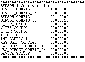
Here is my configuration of the device:

*****************************************************************
SENSOR 1 Info:
I2C_ADDRESS: 0x41
DEVICE_ID: 0x02
MANUFACTURER_ID: 0x5449
*****************************************************************
SENSOR 1 Configuration:
DEVICE_CONFIG_1: 10110100
DEVICE_CONFIG_2: 00010000
SENSOR_CONFIG_1: 00110000
SENSOR_CONFIG_2: 00000101
X_THR_CONFIG: 00000000
Y_THR_CONFIG: 00000000
Z_THR_CONFIG: 00000000
T_CONFIG: 00000001
INT_CONFIG_1: 00000001
MAG_GAIN_CONFIG: 00000000
MAG_OFFSET_CONFIG_1: 00000000
MAG_OFFSET_CONFIG_2: 00000000
DEVICE_STATUS: 00000000
*****************************************************************

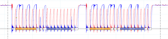
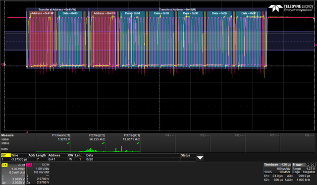
So I write to the Address 0x41 and the register (0x10 + trigger ) 0x90

And then the read of 5 bytes. The 5th byte is not the CRC. it is the next register in line.

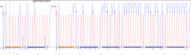
Lets hope the scope image gets the proper resolution.

Please help!

Is it possible to review the TMAG5273 Code?

  • Hey Andreas,

    Thanks for considering to use Texas Instruments.  So there is a note in the datasheet section 7.5.1.3.3 about CRC not being supported if the data length goes over 4 bytes and it advises to use successive read commands for streams of data requiring CRC.  As such, let me know if you still encounter issues when you only ready 4 successive bytes or less.

  • Hi,

    So you say that I'm reading more than 4 data bytes? ref img. Please advice

    best regards

    Andreas

  • Hey Andreas,

    Sorry about that, I should have read through your details a little more closely.  If I understand correctly, you reconfigured the device address to 0x41, then you are trying to trigger through i2c successive 1-byte I2C read of temperature , x, y, and conversion status followed by the CRC.  As such, I think you need to configure INT_MODE in INT_CONFIG_1 to 3h or 4h.

  • Hi,

    No, in the initiated post I'm trying to describe a standard pattern (3 byte -> [Address] + [register & trigger] + [Address , read bit]). Not the 1 byte I2C read (8-16). How do you believe the INT_Mode is related to the CRC byte? I'm receiving updated conversion using the trigger bit and standby mode.

    Best regards

    Andreas

  • Hello Andreas,

    Thank you for clarification.  You are correct, INT_MODE is not relevant here, I saw INT pin in the trigger_mode field field and subsequently conflated Int_mode with standby mode.  Your register settings appear to be correct.  It looks as though you might have updated the i2c scope shot as I previously downloaded an image with a secondary address of 0x41 from your original post and the image display now has a secondary address of 0x35.  As you noted, there does seem to be something wrong with the CRC. If I use the crc calculation method presented in the datasheet for the 4 data bytes (0x44, 0xF0, 0x00, 0x1E) leading up to the CRC byte, I get 0x24, which is different than the 0x00 returned.  I do not see a anything in the transmission to justify an error in the CRC.

    You mentioned previously that it looks like the byte that should be the CRC is actually the data from the next register in the register map.  Reading successively from T_MSB, T_LSB, X_MSB, and X_LSB, this would be Y_MSB.  I presume you confirmed this from subsequent transmissions.  Can you confirm?

    Also can you provide an image of the part markings or the purchase information?  My team can use this then to trace if there are any particular problems with the lot you purchased.

  • Hi again,

    Thanks for investigating further.

    >It looks as though you might have updated the i2c scope shot as I previously downloaded an image with a secondary address of 0x41 from your original post and the image display now has a secondary address of 0x35.

    Yes, the prev img was taken with our PCB. It has too long rise time. Consequently, the frequency is lower than the configured 1Mbps. The CPU waits for the signal to rise above the threshold before doing the drop. The replaced img from the initial post is taken with the EVM and it is configured with a lower std frequency.

    >Can you confirm?

    Yes, I can confirm that it is the next register when reading through all the registers.

    The 3 byte standard read, is it suppose to send CRC on the 5 byte regardless of the requested register? 

    I will get back to you with the purchase information. I have requested the intel.

    The following is from the EVM board.

    And our inhouse PCB with exaggerated soldering.

    Best Regards

    Andreas

  • Here is the requested purchase information for the PCB. Unable to find the EVM purchase information.

    We received the TI Sensor Control Board and utilized the web version to access the TMAG5273. I was hoping there was CRC communication functionality there. I could at least confirm the configuration. (https://dev.ti.com/gallery/view/7472171/TMAG5x73EVM_GUI/ver/2.0.0/)

    I haven't needed to do TI support earlier. Is it possible to get some extended support from Texas Instrument somehow? Or is this the only point of contact?

    Best Regards

    Andreas

  • Hello Andreas,

    Thank you for providing that information.  I have synced with my team on this particular.  We need to conduct some tests of our own to see if we can duplicate what you are seeing.  We should have some conclusion tomorrow.

    We do have field offices in some cities.  However, if the field personnel are unfamiliar with the device of interest, they may be similarly reaching out to representatives of the relevant product lines here.

  • Hey Andreas,

    Can you tell me what speed your i2c clock is running at?

  • Hi, 

    I've tried using 1000 kHz (Fast Mode Plus) and 100 kHz (Standard Mode).

    Is it possible that a slow rise time on the SCL can result in missing CRC?

    best regards

    Andreas

  • Hello Andreas,

    We do not expect the slow rise time to be the issue and if it was it should affect all the data and not just the crc.  We have tried duplicating your results and are getting the expected CRC values.  Can you provide a scope shot of a standard 3-byte I2C read starting at register 0h?  This will confirm that your configuration registers are properly set up yet yielding irregular results.

  • Hi,

    Here is the scope shot of the 3-byte I2C read starting at register 0h, 1MHz:

    Can you please provide the configuration you are using and a scope shot of the successful 3-byte CRC read back?

    Best regards 

    Andreas

  • Hey Andreas,

    Here is a scope shot of standard 3 byte read with CRC enabled.

  • Hi,

    Can you also provide the configuration of all the registers?

    Best Regards

    Andreas

  • Hi again,

    I tried to replicate what you have provided in the scope shot.

    Upfront of the scope shot I only configure register 0 - 3 and then the device address to 0x41. All Single writes.

    I've change the baud to 100 KHz to match your C2 clock freq (96.2 kHz while I get 98 kHz).

    Please provide you configuration, version of chip / marking etc, anything you can provide can maybe helpful.

    Best regards

    Andreas

  • Hello Andreas,

    One of our test engineers ran the test on a TMAG5273A2QDBV.  All registers not displayed in the read back should have been the default power up values.  I will double check with him though.

    Device_Config_1: 94h  
    Device_Config_2: 10h
    Sensor_Config_1: 30h
    Sensor_Config_2: 05h  
    X_Thr_Config: 0h
    Y_Thr_Config: 0h
    Z_Thr_Config: 0h
    T_Config: 0h
    INT_Config_1: 0h
    Mag_Gain_Config: 0h
    Mag_Offset_Config_1:0h
    Mag_Offset_Config_2:0h

    Have you observed this issue on multiple devices?  If you have not already, I would suggest looking to see if this behavior repeats on other devices.  Also, it might help if you fill out a return request.   Then our team can see if you got a bad part or bad batch of parts or if the part was somehow stressed to the point of exhibiting this behavior. 

    If you can isolate the device and communicate with a logic analyzer and see the correct CRC, then it might indicate that there is something about the transmission in your present setup that is tripping up our device. If that is already what you are doing, may we might need to look a little more closely at some of the interface timing specs and individual pulses in the transmission. 

  • Hi,

    These values are not default values:

    Device_Config_1: 94h  
    Device_Config_2: 10h
    Sensor_Config_1: 30h
    Sensor_Config_2: 05h  

    However these are:

    X_Thr_Config: 0h
    Y_Thr_Config: 0h
    Z_Thr_Config: 0h
    T_Config: 0h
    INT_Config_1: 0h
    Mag_Gain_Config: 0h
    Mag_Offset_Config_1:0h
    Mag_Offset_Config_2:0h

    > Have you observed this issue on multiple devices?

    I have provided info regarding the devices I have tested above (purchase info and chip picture). The behavior are the same on both PCB and eval board. I have tested from a arduino env and a stm32 hal env.

    I don't believe I have "stressed out" the sensor.

    I have the TI Sensor Control Board (The Texas Instrument MCU to interface the TMAG and other stuff). Can you send me the code for reading out the CRC in your TI environment? (Code to program the TI Sensor Controller board)

    I have tested the EVM GUI but unfortunately I cannot find functionality to read std i2c 5 b with CRC messages in this GUI.(https://dev.ti.com/gallery/view/7472171/TMAG5x73EVM_GUI/ver/2.0.0/)

    As stated above, I have not received the CRC on any of the TMAG5273 devices.

    best regards 

    Andreas

  • Hello Andreas,

    Yes only the configuration registers were changed.  Thank you for confirming that at least two different devices have this issue.  Im not specifically saying you broke the device.  Somewhere along the transit from fabrication, packaging, or placing the device on the EVM pcb, the device could have experienced some esd event or something else that has led to this behavior.  Alternatively, the screening process we have in place may be inadequate for catching this particular flaw with the device. Without my team looking at your faulty device and doing further investigation, it is difficult to pinpoint a definitive cause for what you are seeing.

    I am not the original author for the gui software or the c code of the evm, therefore I am not able to provide a quick patch for the GUI to test the CRC feature you are interested in.  However, I was able to strip down part of the original c cod to write to the configuration registers and perform 1 standard  3-byte i2c read.  You will need to use the jtag pins on the sensor controller board to program the microcontroller.  By default, the header for those pins is not populated.TMAG5x73EVM2.zip

  • Hi,

    Thanks for the source code. I finally had the time to get your program up and running on the SCB. I installed the code composer and the env - sdk for the cpu and changed the I2c startup configuration to i2c2 for pn4 sda and pin5 scl. Maybe some sensor detection stuff that went wrong (ref TMAG5x73EVM2.zip).

    I used the DFU to update the program. (ref User’s Guide TMAG5x73 Evaluation Module -  slyu058c.pdf 4.1.2.1 - Updating Firmware on SCB) serial bsl or short DFU TP's. The bootloader fails status(11) = iString indicates a vendor specific error, but the LM Flash Programmer downloaded and verified successfully. 

    And here's the shot:

    So Finally a CRC!

    There are some difference in the request (its requesting 5 b). You didn't get 5 b request in your scope shot so I guess it's not related? Otherwise there are some gap in between each 8 b. I will try to adapt to get the same behavior. I let you know how it goes.

    best regards

    Andreas

  • Hello Andreas,

    Glad you were finally able to read a proper crc byte.  Sorry we did not get you there sooner.

    Im not sure I follow your 5 b comment.  The scope shot provided from our test engineer involved a read commands issued from a PXI module and not from our sensor controller board.  The ByteCount I defined in the c code is used by the readMultipleRegisters function which then passes that variable into another function called i2cReceieveArrays which loops through the byte count (4 data bytes + crc byte).