This thread has been locked.

If you have a related question, please click the "Ask a related question" button in the top right corner. The newly created question will be automatically linked to this question.

Sensing ~ 20mm distance with +- 1mm accuracy- suggested part?

Other Parts Discussed in Thread: LDCCOILEVM, LDC1614EVM

Hi there,

We are looking for a method to sense distance between an actuator arm and a mating surface. I wanted to ask if you had a suggestion for sensor technology that could work for this application.

Some details:

  • The mating surface is plastic, but is mounted to a steel plate, so inductive sensing could be used to sense this steel plate, the plate is 23 mm from the sensor
  • A magnet can be embedded in the plastic mating surface with a minimum distance of 17mm to the sensor
  • Need a sensing accuracy of +- 1mm
  • The mating surface is not even, so a capacitive sensor would not be able to locate the correct position

I looked at Hall effect and inductive and believe inductive would be better, as I am not sure if accuracy of 1mm is possible with hall in this application.

Let me know if you have a suggested sensor or need any more details.

Cameron

  • Hello Cameron, 

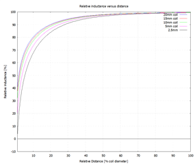
    Inductive sensing is a good option here. One consideration to keep in mind is that your sensing range is dependent on your sensor coil diameter. For an inductive coil, we recommend a max sensing range of 100% of the coil diameter. As your metal target gets further away from the sensor coil, the amount of change in the output is reduced (see graph below) but it is still feasible to sense 1mm change of a metal at 23mm away from the sensor coil. I would recommend starting with the LDC1614EVM and the LDCCOILEVM which has different coil sizes for prototyping. 

    For magnetic, it would depend on how large of a magnet you can use. We have a MAGNETIC-SENSE-ENHANCED-PROXIMITY tool that can be used to simulate the magnetic field and sensor response for different magnets and devices if you want to pursue a magnetic design. 

    Best Regards, 

    Justin Beigel

  • Hi Justin, thanks for the info! That is very helpful.

    One more question- the place we are mounting this sensor will have either a steel or aluminum backing (the sensor coil will be mounted on a solid metal plate) behind the coil.

    Would a metal mount behind the sensor affect it in any way? Or is it ok to operate this way?

  • Cameron,

    A conductor other than the target near the inductive sensor will complicate detection of the intended target.
    The reason is that eddy currents are formed on the nearby conductor, and these in turn interfere with the magnetic coupling between the sensor and the target.

    If you can change the plate behind the sensor to resemble more of a grid-like pattern it will suppress the eddy currents, which should allow detection.
    Some examples can be seen in a app note EMI Considerations for Inductive Sensing.

    Figure 1 & 2 from the app note illustrate the idea.

    The other option might be to add some distance between the sensor coil and the metal backing via a non-conductive spacer.

    I hope this helps. Please let me know if you have any questions.

    John

  • Hi John,

    Thanks for the reply. OK- that is useful to know.

    Would adding this pattern to the bottom layer of the sensor PCB be sufficient, or is a gap still needed to the solid metal plate?

    If a gap is needed, what would be the minimum gap needed?

  • Cameron,

    One way to position the mesh is to put it on the bottom layer of the sensor's PCB.

    The hope is the mesh could replace the metal plate, but if your system doesn't allow that, the spacing between the metal plate and the sensor will need to be at least half of the sensor diameter.

    If you decide to go this route, please be sure to do some thorough experimentation for your application.

    The devil is in the details.

    Regards,
    John