This thread has been locked.

If you have a related question, please click the "Ask a related question" button in the top right corner. The newly created question will be automatically linked to this question.

TMP175-Q1: TMP175-Q1

Part Number: TMP175-Q1

Facing issue while writing configuration register with 9 bit resolution (R0,R1 bit) using I2C protocol. Whenever trying to write the configuration register with 9,10 or 11 bit resolution it is always considering 12 bit resolution and showing the temperature register value from sensor with 12 bit resolution only.
For setting the alert pin for higher and lower threshold, I2C read and write works but writing the value to temperature sensor is not working and because of non functional writing operation in temperature sensor it is not comparing the high and low threshold with current temperature and alert pin is not working as expected.
(Note: Alert pin output from sensor is connected to GPIO on Aurix controller)

Thank you.

  • Hi,

    Thanks for posting to the Sensors forum.

    To adjust the resolution, write the converter resolution bits R1/R0 (bits D6 and D5 of the configuration register, pointer register 0x01) to the desired values. The default values for these bits are 00 (9 bit resolution).

    To set the Tlow and Thigh register, write the desired 2 byte temperature data to the Tlow (pointer 0x10) or Thigh (pointer 0x11) registers.

    Can you provide logic analyzer or oscilloscope captures of writing and reading back the configuration register, writing and reading back the Tlow/Thigh registers, and reading the temperature register?

    Best regards,

    Jesse

  • To set the TLow and THigh register, pointer value should be TLow (0x02) and THigh (0x03) and same has been mentioned in datasheet TMP175-Q1. Is my understanding correct or i should try with TLow and THigh pointer register value suggested by you

  • Hi,

    My apologies for the typo. You are correct, the pointer values are 0x02 and 0x03 for TLow and THigh.

    Please provide logic analyzer or oscilloscope captures showing I2C communication writing and reading configuration register, writing and reading TLow and THigh register, and reading temperature register to debug further.

    Best regards,

    Jesse

  • It would take sometime to provide the captures from logic analyzer. Meanwhile I would be providing read and write data information from debugger.

    Following we observed while testing on Trace32 debugger

    1. Configuration Register

    Tx Data:                        Rx Data:

    0x01                              0x0

    0x11                               0x11

    2.TLow Register

    Tx Data:                        Rx Data:

    0x02                              0xFF

    0xFFD(-40 degree)       0xD0

    3.THigh Register

    Tx Data:                        Rx Data:

    0x03                              0x4B

    0x4B0(75 degree)         0x00

    Temperature register is changing its value to 0x1D80, 1B80 or 0x1E80 (This is some relevant data if we convert using 12 bit resolution (0.0625) but it remains same even if resolution bits R0 and R1 are 0 (i.e 9 bit resolution).


    And after changing TLow or THigh value to any other value (like TLow - 0x00 or THigh = 0x640) still temperature register value shows same and GPIO Alert pin will not change its value to LOW(always be in default value state HIGH).

  • Hi Ankita

    Thank you for that information. It helps to confirm that the configuration, TLow and THigh register values are being stored.

    Note that when writing 0x11 to the configuration register, you are setting the the F1 bit to 1, meaning 4 consecutive faults are required to trigger the Alert. Also, the SD bit is set to 1, meaning the device is in shutdown mode and not performing temperature conversions. You can start a single temperature conversion while the device is in shutdown mode by writing 1 to the OS bit. This could be one reason why you aren't seeing the Alert output toggle.

    For clarification, your TLow value of 0xFFD0 is -0.1875°C. -40°C is 0xD800.

    The temperature register values of 0x1D80, 1B80, and 0x1E80 are valid values for both 9-bit and12-bit resolution. Based on your current configuration register settings, you are operating with 9-bit resolution. If you wish to use 12-bit resolution, please set the converter resolution bits R1/R0 to 11.

    Best regards,

    Jesse

  • Hello Jesse

    Thank you for clarifying above mentioned information.
    As you mentioned above, the expected behavior of alert pin is to toggle when alert will appear. Or it should change its state only once like LOW to HIGH or HIGH to LOW.
    Could you please confirm this.

  • Hi,

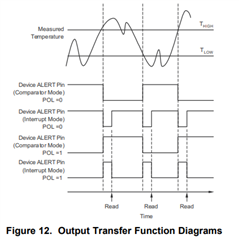
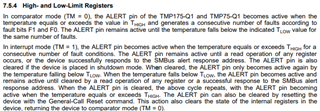
    ALERT pin behavior is shown in Figure 12 of the datasheet and described in Section 7.5.4. 

    Best regards,

    Jesse

  • Thank you for confirming Alert pin behavior and it is working as expected in both modes (comparator and interrupt)
    One more concern regarding resolution bits. The temperature register values of 0x1D80, 1B80, and 0x1E80 are valid values for both 9-bit and12-bit. Is there any way to differentiate resolution bit conversion with mentioned temperature register value. How we should differentiate it is 9 bit or 12 bit resolution data by observing temperature register if in both the scenario will receive same data in register.
    Is the response of temperature register value differentiation is only with respect to conversion time(like 12bit resolution will convert in 220ms)

  • Hi,

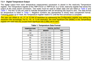
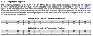
    For 9, 10, or 11 bit resolution, the most significant bits (MSBs) in the Temperature register are used with the unused least significant bits (LSBs) set to zero. In other words, bits D6, D5, and D4 of Byte 2 of the Temperature register are impacted when changing the resolution. Please find additional information included in the screenshots from the datasheet shown below.

    Best regards,

    Jesse