This thread has been locked.

If you have a related question, please click the "Ask a related question" button in the top right corner. The newly created question will be automatically linked to this question.

LDC0851: Trouble getting coil working on LDC0851

Part Number: LDC0851

Dear TI,

I'm working with the LDC0851 and have specced several coils that I would like to try out to experiment with sensing distance. I have a 60mm, 40mm and 30mm diameter coils, each of 8 turns - 0.15mm/0.15mm track width/spacing. According to the coil designer these should have inductances of 9.447 µH, 5.523 µH and 3.711 µH respectively. In this calculation I left LC sensor capacitance as 1000pF as I am unsure how to determine this. I had these coils manufactured on a 4-layer board, with 1oz layers (including inner layers).

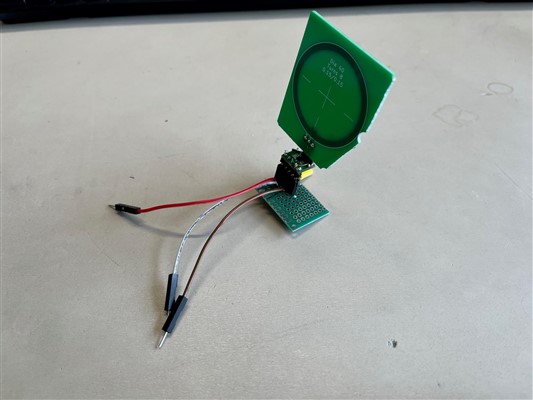
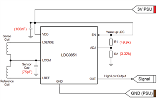
I have started with the 40mm coil, and have this assembled on a perfboard assembly according to the low power operation circuit in Fig. 30. Here, R2 was picked according to ADJ code 1 and Csensor determined by Eq 8 to be 75pF (Cboard estimated to be 5pF). I am powering this with a PSU set to 3V, and monitoring the output pin on an oscilloscope. It should be noted that all caps (power decoupling and Csensor) were assembled directly on the breakout board, close to the IC.

However, when approaching the sensor with several metal objects of various sizes (another coil, a box cutter, probe test leads, a spare PSU) I am not getting any signal from the output pin: i.e. it remains high.

When I make a loop on my oscilloscope lead and bring that close (almost touching) to the coil I do see a waveform of approx 30MHz, 200mV peak-to-peak and when I interrupt the EN pin the IC draws nearly no power and stops the waveform, so all in all I'm confident that the IC is working. Have I made any errors in my passive component selection or is my setup otherwise not appropriate? Looking forward to any feedback on this.
  • Tal,

    Would you please provide some oscilloscope captures of the three input pins, a schematic of your circuit and the spreadsheet tool you used for your calculations?

    Regards,
    John

  • Hi John,

    Thanks for your reply! I will be back in the office tomorrow again and will make those oscilloscope captures. Do you mean captures from the three pins of the coil or of the perfboard assembly (the three dupont cables)?

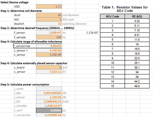
    To preface those oscilloscope captures I have attached a schematic of this circuit, and the spreadsheet tool I made based on the equations and design procedure of the datasheet. BIP Coil Calculations LDC0851 20230602.xlsx

  • Thank you Tal.

    If possible, the three waveforms should be measured at the LSENSE, LCOM, and LREF pins of the LDC0851 while the coils + device are in normal operation.

    Regards,
    John.

  • Dear John,

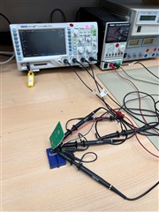
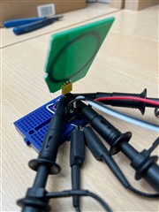
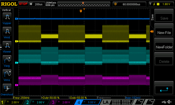
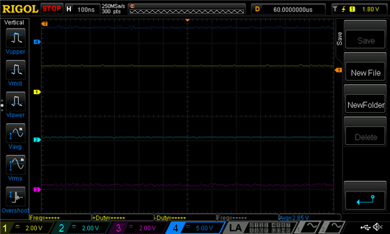
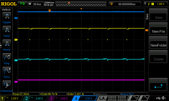
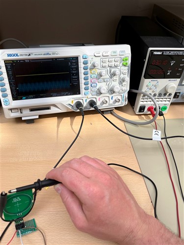
    Please find the captures attached, including a picture of the setup.I added two captures (different time base) with and without a coil attached (see file name for which is which).

    CH1 = LCOM (yellow)
    CH2 = LSENSE (light blue)
    CH3 = LREF (pink)
    CH4 = OUT (dark blue)

    With coil:

    withCoil 1

    Without coil:

  • Tal,

    This might sound kind of weird, but can you measure or estimate the self-resonant frequency of your coil?
    This is the frequency where it is on the cusp of acting like an inductor or a capacitor.
     The sensor frequency need to be at least 25%-30% lower than the self-resonant frequency.

    regards,
    John

  • Dear John,

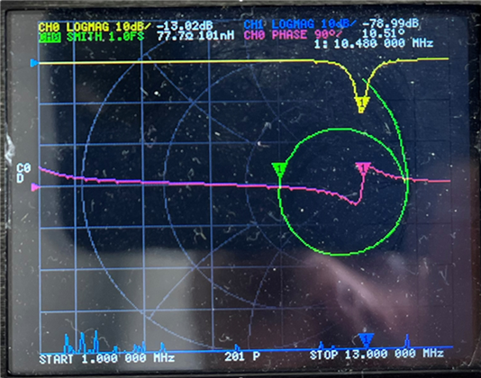
    I checked with a VNA and as far as I can tell the self resonant frequency is 10,48MHz. In the excel tool I entered 10 MHz as the sensor frequency. With this coil, can (and should) I adjust the LDC to use a sensor frequency of say, 8MHz in order achieve that ratio between the sensor and the self-resonant frequency? Or should I redraw the coil for a different inductance / self-resonant frequency ratio?

    Best regards,

    Tal

  • Tal,

    Thanks for the add'l data. Did you remove the 75pF cap for these measurements?
    If not, would it be too much trouble to remove it and re-run the measurements?

    If the cap was removed for the measurements, then the coil by itself looks - from the plot - like it has three resonant points.

    The first one is when the green curve first intersects the horizontal axis just after the start of the frequency sweep.
    As a guess, the frequency of intersection is around 2MHz to 5MHz.
    For frequencies below this value the sensor acts like an inductor. As the frequency increases past this point the curve moves into the lower half of the impedance plane, the phase becomes negative, and the coil looks like a capacitor. 

    As the frequency continues to increase the green curve hits the horizontal axis again, this time near the center of the plot.
    At this point the coil looks like series resonant circuit with a 10.4MHz resonant frequency. This represents the point where - for increasing frequency - the sensor transitions from the lower (capacitive) half of the impedance plane to the upper half of the plane where it starts to look like an inductor again.

    As the frequency increases towards the end of the sweep, the curve loops back down to the horizontal axis again at around 13MHz, intersecting the axis near the first point. 

    If you were to increase the frequency sweep further, you might see the curve loop like this several times until the parasitic capacitance completely dominates and the curve stops.

    So for this sweep you have two regions where the sensor looks inductive. The first is from 1MHz to around 2MHz-5MHz. The second is 10.4MHz to 13MHz. 
    For the other frequency regions, the sensor looks capacitive and the LDC0851 won't be able to drive the sensor with a useful waveform.

    For this sensor, please consider the first point as the self-resonant point and pick a resonant cap that will support a sensor frequency 70% of the first point's frequency. The LDC0851 data sheet table doesn't give a minimum sensor frequency, so this proposal is strictly experimental. Please give it a try and update this thread with the results.

    Juist so you know, replies may be delayed due the the US July 4th holiday.

    Regards,
    John

  • Hi John,

    Thanks for the comprehensive response. And yes, the 75pF cap was removed for these measurements.

    Apologies for the basic recap, but if I understand your (experimental) route this would entail:

    1. Take the first intersection point (VNA gives me 6.1MHz, Z = 1.31kΩ)
    2. Use Eq. 6 in the LDC0851 datasheet to determine Ctotal (and thus Csensor)
    3. Place this Csensor between Lcom and GND
    4. Do another test on the LDC output with the oscilloscope

    However, in step 2, how would I determine Lsensor? At 6.1MHz the sensor does not have an inductance.

    I am not tied to this sensor coil and could change the amount of windings or spacing if need be. If I need to redesign the coil to fit more standard parameters, I could also do that provided I know what to aim for Slight smile

    Thanks again!

  • Tal,

    Before ditching your current coil design, please try an experiment.

    The hypothesis is the varying inductive/capacitive behavior of the coil versus frequency is causing problems.

    So please try calculating and implementing a sensor cap that will give a frequency less than the lowest-frequency crossover point of the horizontal Z-plane axis in the most recent plot.

    Please update this thread with the results.

    Regards,
    John

  • Hi John,

    Perfect, but how can I calculate C-sensor through, f_sensor? Given thatf_sensor is inductance dependent - and the inductance is zero at the given frequency? Thanks!

  • Hi John,

    I've managed to get the current coil to work, with a 160pF cap. However, the sensing distance is a little disappointing at approximately 2mm. With a 40mm diameter coil I had expected something around 15mm - 20mm. Perhaps I should give a side-by-side coil a try, but before I make that overhaul, are there any ways to optimize the range of the current coil?

    I tried a ferrite sheet on the back of the coil, but this lead to a continuously LOW output. Will I need to select a new sensor cap for that application? Are there other ways to improve the sensing distance?

    Thanks!

  • Tal,

    What is the frequency of the sensor waveform? Is it close to what is calculated with the equation shown earlier in this thread?

    Regards,
    John

  • Hi John,

    The frequency is 3,6MHz  However, I was not sure how to apply that equation (Eq. 6), given that the inductance of the coil would be 0 at the self-resonant point we chose. I chose an incrementally higher capacitance until I experimentally landed on 160pF.

    Regards,

    Tal

  • Tal,

    For these calculations, its best to use a frequency less than the self-resonant frequency.

    Just to confirm, the frequency where the curve first crosses the horizontal axis (red circle below) is around 6.1MHz?


    We usually advise no more than 70% of the self-resonant frequency, so 3.6MHz should be okay if 6.1MHz is the first axis-crossing frequency.
    So if you can measure the inductance around 3.6MHz and use it in the equation to solve for C, then it should work.

    Regards,
    John

  • Excellent, thanks for pointing that out. I have done that and have been able to improve the sensing distance to approximately 10mm at a first glance. I have some more questions regarding a smaller target size and generally improving the sensor for our specific application. However, this follow up question contains information that I can not share publicly. Is it possible to have a separate discussion via DM? Thanks in advance!

  • Tal,

    I will close this thread send you an E2E friend request.
    Once the request is accepted we can communicate via private messaging.

    Regards,
    John