This thread has been locked.

If you have a related question, please click the "Ask a related question" button in the top right corner. The newly created question will be automatically linked to this question.

TIDA-010249: IEPE vibration sensor design

Part Number: TIDA-010249
Other Parts Discussed in Thread: OPA2320, DAC5311, THS4551, TVS3301, TVS2201, TVS2701, INA851, TVS2700

Hi,

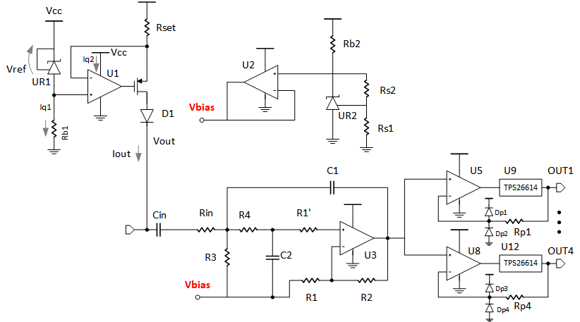
We are looking to create a new design to interface industry standard IEPE sensor. We have taken reference from TIDA-010249 reference design of TI.

The design has requirements as below:

1) IEPE Sensor specs - 100mv/g sensitivity, 10-12V Bias voltage, 0.5mA to 8mA current

2) ADC is not required. Rather, the sensor signal is simply to be buffered into multiple outputs with levels (bias and signal) same as the input signal.

2) Assume that the fixed current source, HPF, and buffer section can be utilized as such from TIDA-010249.

3) Wire break and short circuit checks needed on both input and output.

4) Need EMI and surge protection on the inputs and outputs.

Can you suggest a suitable LPF+output driver stage for this after the OPA2320 stage?

Regards

Gaurav

  • Hello Gaurav,

    1- for variable current source up to 8mA, I suggest using DAC5311 (8bit tiny DAC), followed by a two stage current source like the ones here , OPA2990S can be used to shut down the current source if needed.

    2. are you just filtering/buffering the signal? or doing level shift/RMS detection?

    3. we have a new driver INA851, which can be used as single chip to implement the front-end which is now done by OPA2320 and THS4551

    4. please elaborate on what is needed on the output, wire-break on the input can be done like TIDA-010249 if AC coupled. do you have AC coupling?

    5. for surge protection TVS3301 can be used followed by some series resistance. please provide more details on the input port to suggest a protection scheme. if output is low impedance buffer, protection is a bit tricky. you would need TPS26614 in series followed by TVS2701 or TVS2201 based on your maximum output operating level.

    6. do you need a single-ended driver stage? if would be helpful if you describe what your design will do,

    (e.g: buffering 20kHz 5-17V signal, driving it out single-ended, with gain of 1, and current drive capability of 10mA with min. load of 1kOhm, and 20pF ..... etc.)

    Kind Regards,

    Ahmed

  • Dear Ahmed,

    Thank you for your reply.

    1. I will check for the current requirement and get back. Most probably, we can work with a fixed current source.

    2. Only filtering/buffering the signal. Sensor has a frequency response from 0.8Hz till 15kHz.

    3. We do not need a differential output, but only 4 buffered outputs same as the input sensor signal. INA851 looks very costly for usage in this case.

    4. Yes, AC coupling. Wire short on the output is to be protected from.

    5. The device shall be installed close to high voltage transmission lines and in industrial EMI surroundings.

    6. Yes, we need single ended driver stage only (4 outputs), with gain of 1. I shall get back soon regarding output drive and load.

    Regards

    Gaurav

  • Hello Gaurav,

    it is not clear if you are buffering the signal as is or doing scaling down to lower voltage levels. also after AC coupling the signal is bipolar, are you going to use bipolar supply for the signal chain or single rail supply? which supply level(s)? how the unit is powered?

    Regards,

    Ahmed

  • Hi Ahmed,


    The unit is powered by 24V. We simply need to filter and buffer the signal it to give a clean copy of the input. The output should remain at the same bias levels at the input (around 10-12V). Is it clear now?

    As I understand the input signal shall be positive only, with DC level around the bias voltage. So after AC coupling, the same common mode needs to be inserted.

    Regards

    Gaurav

  • Hello Gaurav,

    sorry for the late response! the last message went off my radar.

    so I'm repeating here your assumptions

    - unit is 4 ch buffer/filter with IEPE input , I assume +/-10V 

    - unit is powered by 24V

    - fixed current source powered by 24V

    - DC bias of the input 10-12V

    here is my suggestions:

    - use single 24V power for the unit. that means all opamps should be high voltage opamps

    - keep the signal level high, no attenuation (unless you need it for some reason)

    - input HPF attenuator should have only 2:1 attenuation, followed by non inverting filter of a gain of 2. not attenuating the singal should in general give better SNR.

    - that said, I would choose a high voltage OPA instead of OPA2320, 

    - lowest cost options are OPAx191, OPAx192, and OPAx197, they differ in noise, BW, and Iq. they have enough SR,current drive, stability with capacitive load  to support the IEPE signal.

    - implement the 4 buffers/filters using quad version of those amps (PA419x) or the dual amp (OPA219x) if your layout requires that. this should be. you can implement the filter using multi-feedback.

    - you will need to shift the signals by a fixed value (11V should be reasonable), this bias or common-mode should be routed to the input HPF, the non-inverting buffer, and the filters/buffers which should be implemented as difference amplifiers to provide this offset.
    - as the bias voltage is not critical in this application. I would assume converting input bias into fixed bias of 11V for all outputs is ok.
    - it is clear that the outputs will be voltage outputs, not IEPE-like. they still can connect to IEPE module inputs if the current source is turned off.

    - I hope this info is helpful.

    - for the input/output wire break, and output short circuit checks. how you want to report the result of those checks? any other output than the 4 buffered outputs? can you provide more information about the complete interface to the module?

  • Thanks for the detailed inputs Ahmed. I too was busy collecting more data from the customer.

    - Yes, the outputs of the card shall connect to IEPE analyzer module inputs as usual, with the current sources turned off. As such, I dont see the need of a high current drive on the outputs.

    - Do you think there shall also be a need of a LPF before the output stage to shunt out any high frequency noise from the OPAMPS? The sensor freqeuncy response is from 0.8Hz till 15KHz.

    - The current range mentioned for the sensor is upto 8mA. I guess we shall keep it around 4-6mA fixed to not cause issues with varying sensor connections in the field.

    - We dont need to report the wire break or short. Instead, we need to prevent the onboard supplies (most probably an isolated supply followed by an LDO), and other circuitry from a fault.

  • Hello Gaurav,

    - Actually doing the filtering in the first stage makes sense. it saves repeating the filtering for each output.

    - I put a simplified schematic for the circuit required below.

    - as you just need protection for inputs/outputs:

    - for the input, the capacitive coupling followed by Rin+R4 will protect the U3 from over voltage.

    - current source is limiting the current so no problem with input short circuit

    - if input breaks the current source will turn off pulling the input to supply level, again no issue.

    - if input has overvoltage this might go back to Vcc, that's why D1 is used to protect against that.

    - for input voltage below ground, D1 and M1 Vds need to withstand the specified input minimum level

    - for output protection, I did use the TPS26614 loop protector, which will implement over current protection, so if output current exceeded 30mA, it will turn off, and retry according to certain sequence.

    - TPS26614 will also protect U5 from over/under voltage, as it will turn off in case OUTx voltage level goes below 0 or above Vcc

    - as the TPS26614 is in the output buffer loop, there is no offset error due to its resistance.

    - to protect U5 inputs against over/under voltage, we have Rp1, in addition Dp1+Dp2 can be optionally used to ensure inputs ESD diodes never turn on

    - if Surge protection is required, then place TVS2700 at the input and the output

    Hope this gives you a good starting point.

    Regards,

    Ahmed

  • Thank you Ahmed. We have sufficient info as of now.

    Shall let you know if anything else comes up.

    Regards

    Gaurav