This thread has been locked.

If you have a related question, please click the "Ask a related question" button in the top right corner. The newly created question will be automatically linked to this question.

TUSS4440: An abnormal signal has been detected on the output OUTA pin

Part Number: TUSS4440

Hi team,

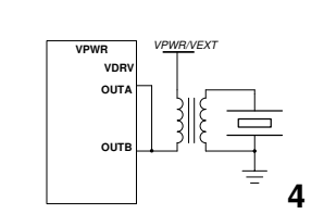
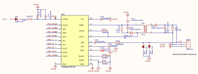
The custom board circuit is as follows: 

The configurations of the register are as follows: 

tuss44x0_regWrite(dev, 0x10, 0x00);
tuss44x0_regWrite(dev, 0x11, 0x00);
tuss44x0_regWrite(dev, 0x12, 0x1E);
tuss44x0_regWrite(dev, 0x13, 0x00);
tuss44x0_regWrite(dev, 0x14, 0x01);
tuss44x0_regWrite(dev, 0x15, 0x00);
tuss44x0_regWrite(dev, 0x16, 0x1F);
tuss44x0_regWrite(dev, 0x17, 0x07);
tuss44x0_regWrite(dev, 0x18, 0x14);
tuss44x0_regWrite(dev, 0x19, 0x3E);
tuss44x0_regWrite(dev, 0x1A, 0x8A);
tuss44x0_regWrite(dev, 0x1B, 0x00);
tuss44x0_regWrite(dev, 0x1C, 0x08);
tuss44x0_regWrite(dev, 0x1D, 0xB9);
tuss44x0_regWrite(dev, 0x1E, 0x02);
tuss44x0_regWrite(dev, 0x1F, 0x00);

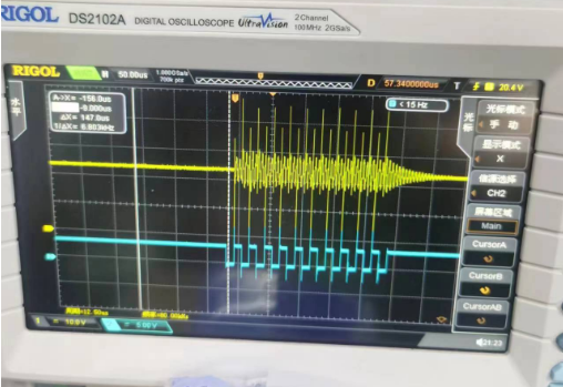
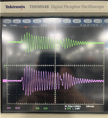
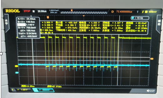
Measuring output terminal outa shows an abnormal signal, only rising falling signal, and no square wave is formed. As shown in the following figure, where yellow is the signal for IO2 and blue is the outa signal: 

Could you help check this case? Thanks.

Best Regards,

Cherry

  • Hello Cherry,

    Thanks for posting to the sensors forum! Please allow us to review the information provided, we will get back to you tomorrow, thank you for patience. 

    Best,

    Isaac

  •  Hi Isaac,

    Thank you for the support.

    Giving some updates: customer changed VDRV to direct connected from VPWR/VEXT and got something as follows:

    (Yellow is OUTA and blue is IO2)

    The configuration is as follows: 

    tuss44x0_regWrite(dev, 0x10, 0x00);
    tuss44x0_regWrite(dev, 0x11, 0x00);
    tuss44x0_regWrite(dev, 0x12, 0x1E);
    tuss44x0_regWrite(dev, 0x13, 0x00);
    tuss44x0_regWrite(dev, 0x14, 0x01);
    tuss44x0_regWrite(dev, 0x15, 0x00);
    tuss44x0_regWrite(dev, 0x16, 0x30);
    tuss44x0_regWrite(dev, 0x17, 0x07);
    tuss44x0_regWrite(dev, 0x18, 0x14);
    tuss44x0_regWrite(dev, 0x19, 0x3F);
    tuss44x0_regWrite(dev, 0x1A, 0x8A);
    tuss44x0_regWrite(dev, 0x1B, 0x02);
    tuss44x0_regWrite(dev, 0x1C, 0x08);

    Thanks and regards,

    Cherry

  • Hello Cherry,

    Thanks for the patience, some comments on the first register configuration they provided: The VDRV_Level_Voltage field in register 0x16 is set too high. It is configured to 0xF, VDRV = VDRV_VOLTAGE_LEVEL + 5 [V]  which means their VDRV voltage must be 20V. If the VDRV voltage requirement is not met, the voltage is not able to cross the programmed threshold.

    When the VDR_Level_Voltage is configured correctly, they should see a similar waveform to the green waveform below.

    The waveform shown in green is the signal coming out of OUTA, and the purple signal is the transducer output.

    The second configuration works fine because it is not connected to VDRV since they are using VPWR/VEXT. The yellow signal looks a bit noisy compared to what I showed above but that may be the way they probed the OUTA signal.


    Thank you,

    Daniel Balmaceda

  • Hi Daniel,

    Thank you for the response.

    The customer just want to make sure the output of OUTA should be a square wave, right? Why is it such a waveform as the one shown above? Is it related to configuration? If so,  how should it be configured when an OUTA output square wave is needed? 

    Thanks and regards,

    Cherry

  • Hello Cherry,

    The additional circuitry built around the IC will alter the shape of the waveform being outputted on OUTA. The waveform that they provided on the second configuration, as well as the waveform I provided, is the expected output.

    I hope this helps.

    Thank you,

    Daniel Balmaceda