


Other Parts Discussed in Thread: AWR6843AOP, AWR1642
Hello TI,
While working with CAN on the AWR6843AOP EVM board with CCS 12.0.3 and Radar toolbox 1.10.00.13, I am trying to modify the Object data over CAN example on the AWR1642 BOOST to make it work with my board (still not the case), for that I have the following questions :
1- I saw in a thread that there are certain switch positions for CAN, could you inform me of the ones I need in my AWR6843AOP board once the code is flashed ?
2- The board I use has 2 CAN-FD interfaces, how do I select the one I want to use ? is there a default one ?
3- In the example there is a use of a mmWve CAN Visualizer, is this tool still available (I cannot find it) ? Also are my board + my CAN adapter (which is The following) compatible with its use ?
PS : I already found the CAN visualizer in ti\radar_toolbox_1_10_00_13\tools\visualizers\mmwave_can_visualizer, though I'd still like to confirm the compatibility.
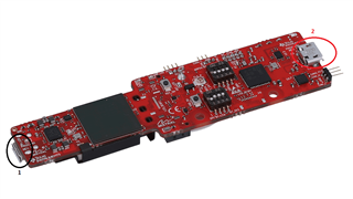
4- A last thing, when using CAN, can I use the UART port (Number 1 in image) simultaneously, or do I only use the port 2 for supply needs ?
Thanks and regards,
Lilia.
