This thread has been locked.

If you have a related question, please click the "Ask a related question" button in the top right corner. The newly created question will be automatically linked to this question.

IWR6843AOP: Initial configuration/flashing

Part Number: IWR6843AOP
Other Parts Discussed in Thread: UNIFLASH

Hi,

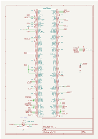
I have developed a PCB with an IWR6843AOP, loosely based around the EVM design board.

I have exposed the following pins:

- Crystal
- Connections for flash ic
- RX/TX
- 2nd UART (TX only)
- SOP (PMIC_CLKOUT)
- GND and power supplies

I have tried flashing the chip using uniflash but I can't get a connection to the chip.

Is there any initial configuration I need to do to the chip before I can flash it?

Have I forgotten to expose some crucial pins?

Thanks


  • Hello,

       There are many connection issues are present in the design, 

    https://www.ti.com/tool/IWR6843AOPEVM

    Please follow below EVM schematic connections from latest revision. 

    https://www.ti.com/lit/zip/swrr166

    Complete PCB design files in Altium in the below link.

    https://www.ti.com/lit/zip/sprr418

    Thanks and regards,

    CHETHAN KUMAR Y.B.

  • Thank you for your reply.

    Can you please clarify, are there connection issues in my attached schematic?

  • Hello PJ,

    Please find below points:

    Vout_14synth needs external 1uF capacitor

    Vout_14APLL needs external 1uF capacitor

    There are many mandatory decoupling caps are missing, Please refer below from the EVM schematics

    There are power supply filters are needed to meet the ripple/noise requirement that are not shown in the current schematic.

    QSPI flash need to be compatible with the ROM bootloader with appropriate pull up resistor as per EVM.

    UART port RS232 requires mandatory pull up resistors that are missing.

    Boot /SOP mode (Flashing & functional mode) pins PMIC_CLKOUT, SYNC_OUT, TDO need to have appropriate pull up/down to configure different modes of operation.

    NRESET lines needs cap along with pull up so that, It could be released after the supplies are stable to that it could register appropriate boot mode during the power up.

    NERROROUT, NERROR_IN, WARM_RESET are open drain needs external mandatory pull ups.

    Thanks and regards,

    CHETHAN KUMAR Y.B.

  • Hi Chethan,

    Thank you for your reply.

    I have all the decoupling capacitors on another sheet but I can see now that I have left some import pins floating. I will fix my schematic and try again.

    PJ