This thread has been locked.

If you have a related question, please click the "Ask a related question" button in the top right corner. The newly created question will be automatically linked to this question.

AWR1642: Antenna design confirm for the object position

Part Number: AWR1642

Usual the antenna design for TX and RX at the same side, and the space between RX1 & RX2 is λ/2 at the same horizontal level which shown as below.

It can get the object position by (x, y,) in 2D.

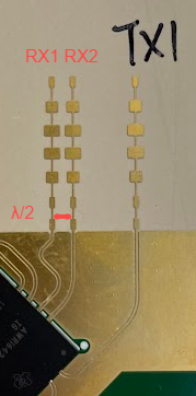
Because of some reason, our design of antenna is as below picture, TX and RX at the opposite side and RX1 & RX2 not at the same horizontal level.

Will it get the same object position (x, y) in 2D?

Many thanks.

  • Hi,

    Having the TX antennas on opposite side (180 degrees) of the RX antennas should be ok.  I would also recommend testing your antennas design performance with HFSS or similar tools.

    Regards,

    Sami

  • Hi Sami,

    Thanks for the information.

    Understood the TX position can be on the opposite side of the RX.

    How about the different of RX (RX1 & RX2 turn 90 degrees and not at the same horizontal level)? 

    Could the object position still calculated with the same coordinate (x, y)?

    Many thanks.

  • Hi,

    Having a lambda/2 spacing between RX1 and RX2 in the elevation plane  will help help improve your angular resolution in the elevation plane, at he cost of the azimuth plane.  So, what you are doing is ok.  I would also recommend that you review your antenna virtual array with your system team to see if you are meeting your senor design requirements,  

    Regards,

    Sami