


Other Parts Discussed in Thread: INA226,
Hi team,
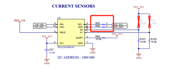
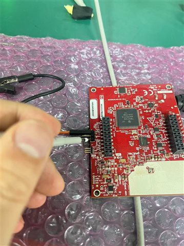
The customer want to use the 4 INA226 chips from the IWRL6432BOOST to monitor the state of power consumption in various modes of the radar. Using MMWAVE_L_SDK_05_02_00_02\examples\mmw_demo example code(no drive changes are currently made, only comments are added). Here's the test code: https://e2echina.ti.com/cfs-file/__key/communityserver-discussions-components-files/118/IWRL6432_5F00_SDK_5F00_05_5F00_02_5F00_00_5F00_02.rar
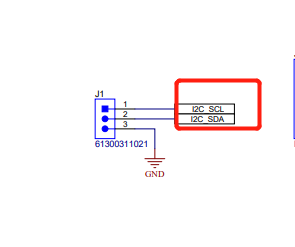
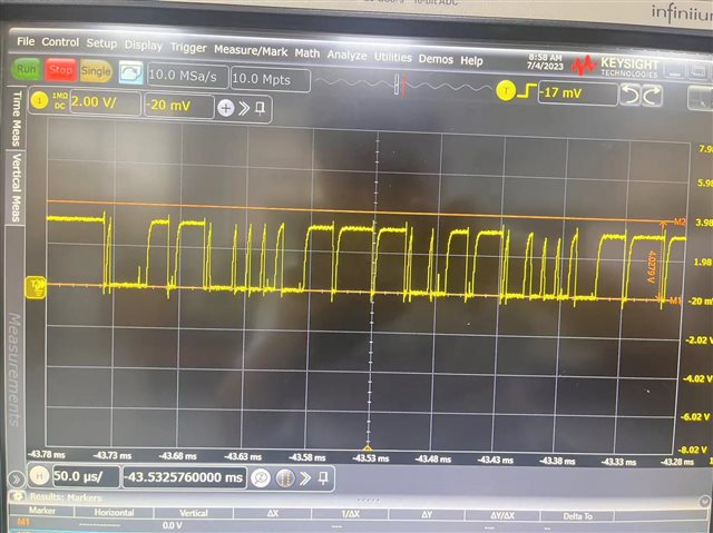
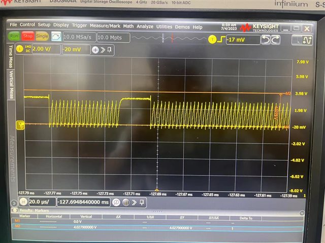
After downloading to the board and running, it's found that I2C was unable to read the INA226 chip power supply values. The I2C bus of the development board was randomly measured and found that the I2C_SDA and I2C_SCL signals were not normal PWM waveforms. The grounds are verified as good.
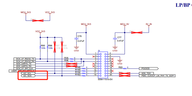
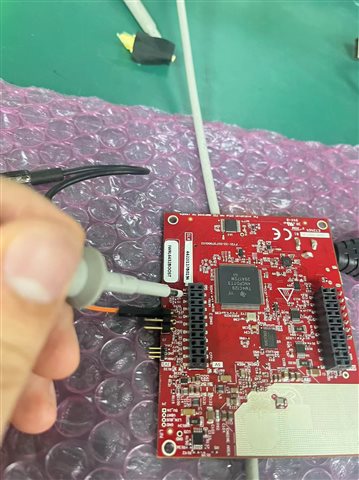
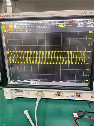
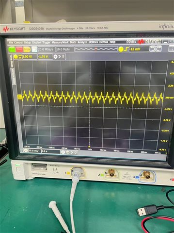
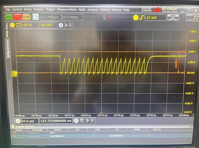
They also tried to pull S1.6 high but INA226 still cannot read the data properly. SCL and SDA signal lines of I2C bus were remeasured and the pulse width of the PWM waveform was still too narrow, possibly the INA226 chip could not resolve the instruction on the bus properly, causing reading data to fail.
Could you help check this case? Thanks.
Best Regards,
Cherry
