Other Parts Discussed in Thread: FDC1004
I have an application using CH0 and CH1 for sensing liquid , and CH2 for a reference sensor. All 3 channels are configured with differential sensor plates. CH0 and CH2 are behaving as expected, but CH1 has some strange behaviour where the readings drift and recover for no apparent reason.
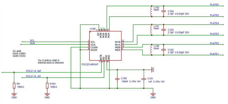
Since CH0 and CH1 are measuring the same vessel of fixed volume of liquid , I doubt it's due to that. The LC tanks are all the same (18uH and 2.7pF) and sensor plates same size. I wondered if the layout and specifically the proximity of ground planes and other signals to the sensor tracks are the cause.
1/ Should the channel signals be "isolated" from other circuit signals by putting a ground plane underneath and along side the channel signals? If so , how close or how far ? Currently I have minimum track-track clearance between ground plane and the one channel signal.
2/ Please can you confirm which pin (either CHxA or CHxB) is the driven output, and the other pin presumably is the input? (I'm assuming it's similar to a crystal oscillator circuit. ) Currently IN0A is routed next to ground plane and other signals, while IN1B is routed close to ground plane and other signals.
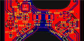
U100 is the FDC2214 ; CH0 has L100//C102 and tracks going to the left, and CH1 has L101//C103 and tracks going to the right.
3/ I would imagine I should put the driven signal next to ground plane and other signals, and the "input" signal away from ground plane/other signals.
Thank you,
Hadyn