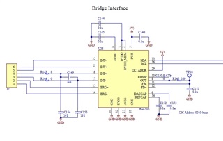
We have tested with the chip and reading PADC_DATA1, PADC_DATA2, PADC_DATA3 directly seems to work fine for our application. The temperature by the pressure transducer is not changing much.
Is just reading PADC_DATA1, PADC_DATA2, PADC_DATA3 directly a valid way to use the chip? (I describe the steps below)
This is a hit a miss proposition because we have some that are reading just fine but on other boards with the chip, I am reading zeros for Pressure (described in detail below). This could be a problem with the boards but I want to make sure I’m doing everything correctly so that I can rule out that the problem is with my firmware.
On the working board I measure the correct 2.5V across BRG+ to BRG-. On the boards returning 0 pressure I have 0V between BRG lines. The excitation voltage is never turned on with these.
The firmware on the boards is identical. It could be a problem with the board, but I want to explore the possibility that this could be caused by a slight difference in IC timing or maybe that my code is poor and I’m just getting away with it on some cases but not in others. Note: The registers listed below are different between the working and non-working boards. I have tried forcing these registers but that doesn't seem to help.
0x22 DAC_ENABLE 0x38 = 0x31, BRDG_CTRL 0x46 = 0x11
Could you look at the data below and give me an opinion of what could possibly cause one board to work and another to return zeros. I have played around with a lot of different timing sicarios and forced some settings that are different but with no success.
(Note: Please use the assumption that the board and the IC are fine.)
Below is my method for reading the Pressure data from the PGA305:
The I2CADDR Pin is tied to 3.3V so I am dealing with Registers 0x20, etc.
Below is the EEPROM of both and the 0x22 Register of both.
I am successfully communicating with both boards over I2C and this is the method I am using to read the PADC_DATA Registers.
I am continually performing these steps every time I access the PGA305 IC.
STEP 1. Set COMPENSATION_CONTROL Register p30
For the I2C interface to have access to the configuration registers,
the IF_SEL and the COMPENSATION_RESET bits in the COMPENSATION_CONTROL
register have to be set to logic one.
I2C_A = 0x20; // Address Page 0
I2C_Reg = 0x0C; // COMPENSATION_CONTROL Register p53
I2C_Data = 0x03; // IF_SEL, COMPENSATION_RESET
STEP 2. Set Gain to the Maximum
I2C_A = 0x22; // Address Page 2. 0x20 + 2 = 0x22
I2C_Reg = 0x47; // P_GAIN_SELECT p5
I2C_Data = 0b00011111; // Maximum Gain using the 5 available bits
STEP 3. Read the 3 Pressure Registers (PADC_DATA1, PADC_DATA2, PADC_DATA3) from 0x22 using registers 0x20, 0x21, and 0x22
EEPROM OF WORKING BOARD. Returning good pressure data
(Measured Voltage between BRG+ and BRG- = 2.5V)
(Note: I updated EEPROM for max Gain in register 0x33 by setting the value to 0x1F)
00 00 20 00 00 00 00 00 00 00 00 00 00 00 10 00
00 00 00 00 00 00 00 00 00 00 00 00 00 00 00 00
00 00 00 00 00 00 00 00 00 00 00 00 00 00 00 00
66 01 00 1F 01 80 02 43 00 01 00 00 00 00 FF 3F
00 00 FF 3F 01 00 00 00 00 00 00 00 00 00 00 00
00 00 00 00 00 00 00 00 07 73 FF 3F FF 3F 01 00
00 00 00 00 00 00 00 00 00 00 00 00 00 00 00 00
FF FF FF FF FF FF FF FF FF FF FF FF FF FF FF 90
EEPROM OF BOARD THAT IS NOT WORKING. Returning pressures of only zero
(Measured Voltage between BRG+ and BRG- = 0V)
(Note: I updated EEPROM for max Gain,
I also update EEPROM 0x60->0x67 to match the working board)
00 00 20 00 00 00 00 00 00 00 00 00 00 00 10 00
00 00 00 00 00 00 00 00 00 00 00 00 00 00 00 00
00 00 00 00 00 00 00 00 00 00 00 00 00 00 00 00
66 01 00 1F 01 80 02 43 00 01 00 00 00 00 FF 3F
00 00 FF 3F 01 00 00 00 00 00 00 00 00 00 00 00
00 00 00 00 00 00 00 00 07 73 FF 3F FF 3F 01 00
00 00 00 00 00 00 00 00 00 00 00 00 00 00 00 00
FF FF FF FF FF FF FF FF FF FF FF FF FF FF FF 90
------------------------------------------------------------------
Register 0x22
PDAC_DATA 0x20->0x22
TADC_DATA 0x24->0x26
DAC_ENABLE 0x38 = 0x31
BRDG_CTRL 0x46 = 0x11
!!! GOOD DATA !!!
PGA305 0x22 (0x20 -> 0x4C)
F8 57 D1 07 2E 1B 19 07 00 10 00 00 00 00 00 00
00 00 00 00 00 00 00 00 31 00 00 1F 00 00 00 00
00 00 00 00 00 07 11 1F 02 00 00 00 43
NOT WORKING PGA305 0x22 (0x20 -> 0x4C)
00 00 00 00 00 00 00 00 00 03 00 00 00 00 00 00
00 00 00 00 00 00 00 00 31 00 00 08 00 00 00 00
00 00 00 00 00 00 11 1F 00 00 00 00 40


