This thread has been locked.

If you have a related question, please click the "Ask a related question" button in the top right corner. The newly created question will be automatically linked to this question.

AWR2944: Noise floor magnitude

Part Number: AWR2944

Hi team,

Some details are as follows:

The software architecture is the ported SDK4.2.3, the transmit mode is in DDMA mode, the waveform is a single waveform with 256 ADC samples per chirp. 384 chirps in total per frame. The horizontal angle target detection range specification is designed to be ±70°.

In the darkroom test, the customer did the antenna pattern gain test, which was similar to what was expected, because the target could not be seen in the angle range of more than ±50°. By exporting the data from the detection_matrix in DSS_L3 memory from CCS's memory browser and plotted in Matlab, the results are shown in the following figure (the x-axis represents the distance unit dimension and the Y-axis represents the Doppler unit dimension, Z axis represents the magnitude. The target of the release is at (107, 34) and the point at (89, 47) is the approximate magnitude of the marked noise floor):

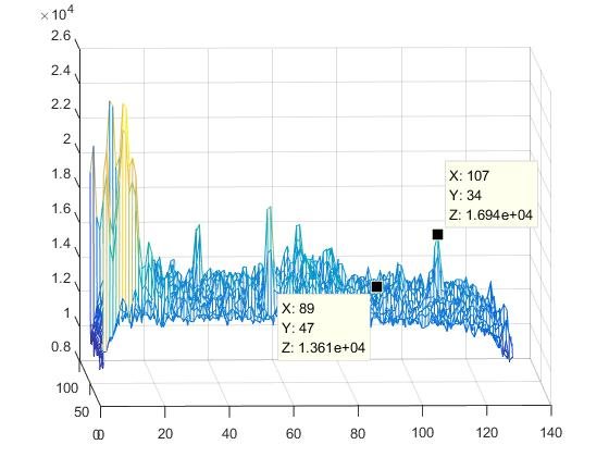
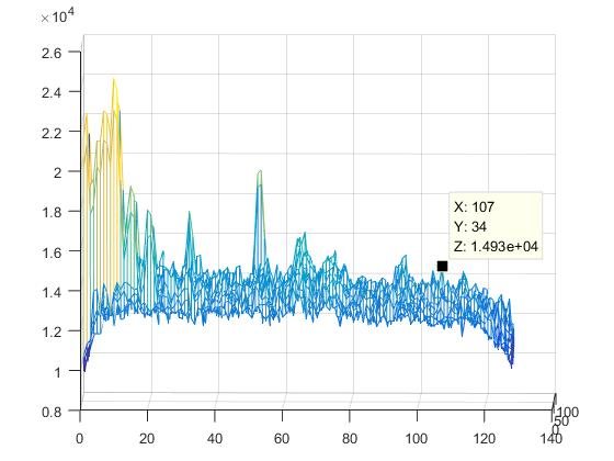
The first plot is the result of the target at 0° in the radar and the second plot at 55° in the radar.

According to the results plot, the problem is that the target cannot be seen because the signal-to-noise ratio of the target at ±50° is not constant enough to limit the alarm threshold. With the antenna pattern test results generally normal, the customer suspects that the problem may be caused by the large noise floor. 

Software with AWR2944 and SDK4.2.3 in the general example of DDMAdemo provided by TI, is the noise floor magnitude of detection_matrix similar to the noise floor magnitude in the figure above?  If not, what might be the possible cause especially during the DPC processing link?

Could you help check this case? Thanks.

Best Regards,

Cherry

  • Hi Cherry,

    The signal strength of an object's reflection will drop as it strays away from the boresight (0 degrees) based on the antenna gain characteristics. That being said, we can look at a few pointers to see if the SNR you are seeing is valid. I have the following questions which you can look at:

    • Can you confirm if the customer is using AWR2944EVM or do they have their custom board with their own antenna?
    • Is this plot of the range FFT after summing across Rx or before? Would it be possible to check for it after non-coherent integration?
    • Have they tested this on multiple devices or just the one?
    • Would it be possible to port the chain to the newer SDK (4.4)?
    • What is the setting of Rx gain? Would it be possible to increase the same?
    • Are they not able to see the signal when performing angle dimension processing?
    • Have they captured the data with any other chirping scheme or modulation and observed this huge degradation of SNR?
    • Can you take stream the ADC data using LVDS and perform processing of the same test setup data capture on MATLAB? (This should take any doubts away from the DPC and isolate the issue to the front end)

    Regards,

    Kaushik

  • Thank you for your answer,we adopt your suggestion  and analysis the ADC data to locate the  issue at the front end。

  • Thanks for your update. Will be closing this thread. 

    Regards,

    Kaushik