This thread has been locked.

If you have a related question, please click the "Ask a related question" button in the top right corner. The newly created question will be automatically linked to this question.

TMAG5170

Other Parts Discussed in Thread: TMAG5170

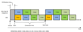
Now we have question for continuous mode. I see registers and if understand well 010b = 2h, in active measurement mode is always low power mode time delay. So this mode is for our purpose (motor commutation )  not good because we have 1ms regulation loop. Minimum time of low power mode between measurement is same 1ms. Do I understand it well?

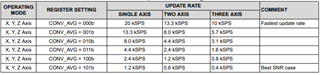
Then I have to use Trigger mode, start conversion on CS pulse. Then I can achieve without filtration 13.3 ksps for 2 channel (angle) sensing, Am I right?

  • Karel,

    This appears to be a typo.  The SLEEPTIME setting applies when OPERATING_MODE is set to 100b (4h) .  In active measure mode, the next conversion will start immediately after the preceding conversion.  The conversion cycle will follow this pattern:

    You should be able to achieve the following sample rates with continuous conversion set:

    If averaging is enabled (2x - 32x), the temp conversion (T_RATE) should be set to once per conversion set to achieve the rates shown above:

    Thanks,

    Scott

  • Ok, thank you Scott. BTW, what do you suggest for sleep mode of our linear motor. Now idea is simple after motor stop we want to set TMAG5170 to sleep mode and use ALERT for waking up microcontroller if external movement is applied on linear motor, then I saw in manual we can set threshold for axis. If threshold is reached alert is activated. Problem is if our motor stop in position near threshold, then it is unstable output of alert signal.

  • Karel,

    This is an interesting question.  If I understand right, you may stop the motor at any position, and then put the system to sleep to conserve power.  While in this state, the user might change the position of either the magnet or sensor which would result in a new input condition.  

    Since the stop position will have a unique input condition, you would need to set the threshold at the time of entering sleep mode, so the target value would seem dependent on your magnetic input range and where the linear motor stopped.  For this, it really would depend on how much motion you wish to trigger the event relative to the changing field.  

    After waking, you would receive alert pulses any time the motor caused the observed input field to cross the threshold unless this were disabled.

    Thanks,

    Scott

  • Hello Scott,

    we are still discussing here, what configuration would be best sensor setup for motor control application. Our motor control application needs to get in 1kHz rate fresh position value. Speed is then computed as numerical differentiation of position, which always brings challenges: To get quality speed signal it is needed low noise and high resolution in position signal. Another issue is, that for speed feedback control is signal time delay always killer. From above requirements: We would like to get angle value in fixed rate 1kHz, angle value computed from highest highest possible count of averaged samples in best possible resolution (12bit?), captured in last 1ms. Angle value in best possible resolution (13bit or 12bit over SPI?)

    Can you advice us, how would be possible to set the sensor? Continouous mode? Or trigger mode with everaging in MCU?

    So there is question for averaging if I use internal classsical AVG filter of TMAG or I will create better filter (window filter).

    By the way, Im a litte confused with 7.5.1.4 Angle and Magnitude Data Definition, there is 1/16 and 1/4 resolution from cordic. So, how can I achieve 1/16 resolution?

    Can we do some small call for better understanding?

    Thank you very much

  • Karel,

    You may use 1x-32x averaging while in continuous mode and not just during wake and sleep mode while using the Alert pin as a trigger.

    Another setting at your disposal is to set the sampling pattern to account for sampling latency of the device.  Since the axes are sampled serially, measuring angle at speed can produce non-linearity.  The device allows you to set the pattern to XYX which will average an x result immediately before and after the Y conversion.  This is referred to as pseudo-simultaneous sampling in the datasheet.  This particular pattern would use the same conversion time as XYZ.

    So, if you need fresh data at a 1 KHz rate, we need to set the sample pattern above 1 Ksps.  In XYX mode you could set averaging as high as 8x and still have new data for each sample.  In Just XY mode, you could set the averaging to 16x. 

    The integrated CORDIC has a resolution of 1/4 degree at the output.  To achieve 1/16 degree you would need to read the raw X and Y channel data and then perform the arctangent calculation in your MCU.

    I have sent you a request to connect, and will be able to send you my contact information for a more direct conversation if needed.

    Thanks,

    Scott