This thread has been locked.

If you have a related question, please click the "Ask a related question" button in the top right corner. The newly created question will be automatically linked to this question.

DRV5056-Q1: Power dissipation of DRV5056

Part Number: DRV5056-Q1

Looking for reference document to calculate power dissipation of the sensor?

  • Hello Prathmesh,

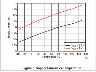
    Thank you for considering to use Texas Instruments.  I am not aware of a specific document that calculates the power dissipation, but here I can give you some methods to approximate that.  For worst case you could use the max supply voltage you expect to supply the part with and the max operating supply current of 10mA.  So if you supplied 5.5V, that would be 5.5V*10mA =  55mW.  However, if you wanted something closer to typical performance, you could take the typical supply value.  Then you could extrapolate the typical supply current from the supply current vs temperature plot shown below. If I presume Vcc = 5V, then the corresponding slope could be approximated to (6.75A-6A)/(120°+25°)=5.172E-6A/°C.  From this could approximate the power dissipation neglecting the device output path by calculating Vcc_typ*(slope A/°C)(operating temperature °).  Now for the output power component, the datasheet specifies a maximum of +-1mA of continuous output current.  We certainly do not need to source or sink that much. If you know the resistance of the downstream component, you can then calculate the max output current, IO, by taking by taking the max Linear range of output voltage, VL= Vcc-0.2, and divide that by the downstream resistance.  There take VL*IO to get the output power dissipation.