This thread has been locked.

If you have a related question, please click the "Ask a related question" button in the top right corner. The newly created question will be automatically linked to this question.

IWRL6432: Visualizer error with sending cfg

Part Number: IWRL6432

Hello, TI guys.

Now I have an unexpected issue, then I need help from you.

I have been developing IWRL6432 product.
I have mentioned several times that I made my own custom board of 6432 by modyfing its EVM.

To find out optimized cfg for my application, I edited its configuration from motion detection cfg offered in SDK 5.1.
(I guess SDK version is not related with this issue)

As following, I attached my cfg,
sensorStop 0
channelCfg 7 3 0
chirpComnCfg 8 0 0 256 4 28 0
chirpTimingCfg 6 63 0 50 60
frameCfg 2 0 200 64 150 0
guiMonitor 2 1 0 0 0 1
sigProcChainCfg 16 8 1 1 4 4
cfarCfg 2 8 4 3 0 8.0 0 0.5 0 1 1 1
aoaFovCfg -60 60 -40 40
rangeSelCfg 0.1 12.0
clutterRemoval 1
compRangeBiasAndRxChanPhase 0.0 1.00000 0.00000 -1.00000 0.00000 1.00000 0.00000 -1.00000 0.00000 1.00000 0.00000 -1.00000 0.00000
adcDataSource 0 C:/ti/mmwave_lp_sdk/examples/datapath/common/testBench/major_motion/adc_data_0001_CtestAdc6Ant.bin
adcLogging 0
lowPowerCfg 1
factoryCalibCfg 1 0 40 0 0x1ff000
mpdBoundaryBox 1 -1.5 1.5 0 3.8
sensorStart 0 0 0 0

And for reference, motion detection cfg downloaded from visualizer is also attached as below
sensorStop 0
channelCfg 7 3 0
chirpComnCfg 8 0 0 256 4 28 0
chirpTimingCfg 6 63 0 75 60
frameCfg 2 0 200 64 250 0
guiMonitor 2 1 0 0 0 1
sigProcChainCfg 32 2 1 0 4 4
cfarCfg 2 8 4 3 0 12.0 0 0.5 0 1 1 1
aoaFovCfg -60 60 -40 40
rangeSelCfg 0.1 12.0
clutterRemoval 1
compRangeBiasAndRxChanPhase 0.0 1.00000 0.00000 -1.00000 0.00000 1.00000 0.00000 -1.00000 0.00000 1.00000 0.00000 -1.00000 0.00000
adcDataSource 0 C:/ti/mmwave_lp_sdk/examples/datapath/common/testBench/major_motion/adc_data_0001_CtestAdc6Ant.bin
adcLogging 0
lowPowerCfg 1
factoryCalibCfg 1 0 40 0 0x1ff000
mpdBoundaryBox 1 -1.5 1.5 0 3.8
sensorStart 0 0 0 0

As you can see, there is only few differences.

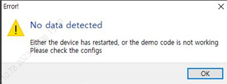
But suddely, visualizer is stopped with error when I send my cfg.
Whether my board or EVM, the same result comes out.

I am confused because there was no problem until I figure out the values using visualizer.
Furthermore, detection data output is out and main MCU take it.

I have no idea what the problem is in this situation.

Let me know if you can help anything for me.

  • Hello,

    Sorry for the delayed response.

    I have mentioned several times that I made my own custom board of 6432 by modyfing its EVM.

    What modifications to the board did you make?

    Which visualizer are you using? What errors are you seeing in the visualizer?

    Can you send some screenshots of what you are seeing?

    You're saying a separate MCU is able to read data over UART?

    Regards,

    Tim

  • Hello,

    *Modification
    - I just made my board with only minimum part to operate radar sensing(6432, DCDC, QSPI flash, RLCs, LED) being the same as EVM.
    * Visualizer version
    - I use visualizer in SDK version of MMWAVE_L_SDK_05_01_00_04.
    * Error Screen shot
    - Image as below
    * MCU
    - I use ST MCU as main function and receive radar data(UART) from 6432.

  • Now, I guess I find out the cause of the error issue.

    I changed cfg parameter frome attached my cfg(in the question thread) only FramePeriodicity in frameCfg command(150 to 200).

    After that, I have had no more error.
    I assume,
    Required performance to signal processing exceed against how 6432 can when the frame rate is too fast.
    Frame Periodicity 150 ms is too fast to do all calculation.

    However, in SDK(any version),
    its figure is described as,
    Frame Periodicity. This field indicates the period of the frame, 32bit counter.This field indicates the frame periodicity, the time gap between successive frame starts.
    Unit: ms
    Valid range:100 to 4294967295 (Limited support in current OOB).......

    There is no supporting range that can operate.

    Is this the reason because of current SDK & 6432 are not for MP?

    I want realistic cfg parameter value range of this, also others parameters.

  • Hello,

    I am happy to here that you found modifying FramePeriodicity would make the chip work. I've put your configuration (with 150ms Frame Period) into our sensing estimator tool: https://dev.ti.com/gallery/view/mmwave/mmWaveSensingEstimator and it is giving me an error as an invalid configuration:

    "With the xWRL6432/1432, burst idle time, which equals burst periodicity - numOfChirpsinBurst(idleTime+rampEndTime)), must be greater than 115µs. Currently it is 82µs. Increase burstPeriodicity, or decrease numOfChirpsinBurst, idleTime or rampEndTime"

    I highly suggest using the sensing estimator tool when constructing your .cfg files so you know that the values you are putting into the device are feasible.

    Regards,

    Tim