This thread has been locked.

If you have a related question, please click the "Ask a related question" button in the top right corner. The newly created question will be automatically linked to this question.

TMP103: TMP103AYFF | VIH is failing

Part Number: TMP103

Hi Team,

Please find the below-summarised table for the temperature sensor values measured.

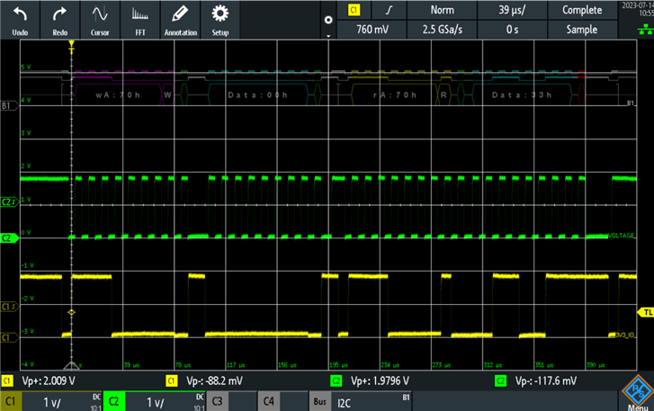
Here Max VIH is failing, The supply voltage is 1.8V and the waveform seems okay. Could you please tell me why? 

  • Table below shows the summariesed data measured
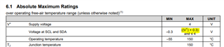
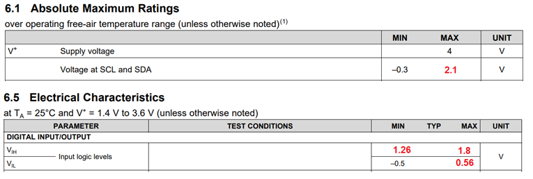
    Sensor-TMP103
    Signal Symbol Min Max Measured Units Result
    TEMP_EPR_I2C_SCL
    VIH 1.26 1.8 2.0188 V FAIL
    VIL -0.5 0.54 -0.147 V PASS
    TEMP_EPR_I2C_SDA
    VIH 1.26 1.8 1.9796 V FAIL
    VIL -0.5 0.54 -0.0882 V Pass

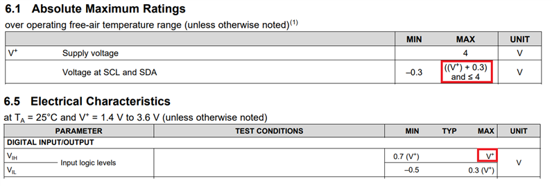
  • The image is taken from the datasheet

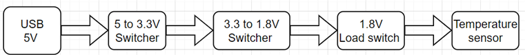
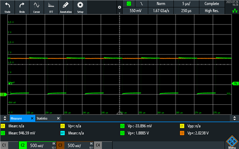
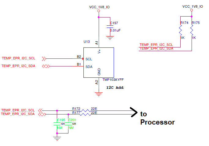
  • The image below shows the Schematics used. and the waveform is probed from R174 and R175 resistors
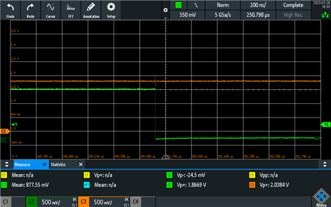
  • Below is the probed image from MSO 
  • Hi Felix,

    I don't see a source of 2V anywhere in your schematic. How are you testing VIH? If you are sourcing current into SCL/SDA pins, you must clamp your instrument at 1.8V. Sourcing current this way would detect the structures responsible for TMP103's unique absolute max spec. TMP103 does not allow SCL/SDA voltages to exceed V+. This limitation comes from the low pin count; other I2C TMP have more pins and don't have this voltage limitation.

    ren

  • Hi Ren,

    1. Below power scheme is used for VCC_1V8_IO generation 

    2. We use MSO to probe the VIH(from resistor R174 and R175). 

  • How do you test VIH?

    thanks,

    ren

  • Hi Ren, 

    Didn't get what you are asking.

    1. We have used Oscilloscope to probe the VIH(from resistor R174 and R175), which was found higher than supply voltage 1.8.

    2. We are measuring the temperature value and found it to be okay.

    3. Clock and Input waveform is also attached below. From the waveform it is clear that VIH is higher than input voltage

  • This voltage level that you show on the oscilloscope is not VIH. VIH is an input specification. The VIH spec is tested by varying the input voltage to see what voltage is needed for TMP103 to detect logic high. 

    The voltage level is determined by your pull-up resistors' supply voltage. Your schematic specifies the voltage as 1.8V. Either your pull-up voltage is not 1.8V, your oscilloscope is not calibrated, or some combination of the two. The only way TMP103 would contribute to voltage level is if the SCL/SDA voltage exceeded TMP103's supply voltage, it would then try to pull down the voltage. That is not the case in your schematic, and the symptom you are reporting is that the voltage is pulled above supply. 

    ren

  • Hi Ren,

    For the pull-up and supply voltage, there is no change. They are shorted to 1.8V supply. From the above discussion what i understood is that.

    • 1.26 to 2.1V will consider as logic 1
    • -0.5 to 0.56V is considered as logic 0

     Please confirm these values if the supply voltage is 1.8V.

    Figure 1 : From the datasheet

    Figure 2 : Edited for our values.

  • Seems reasonable to me.

    ren