Hi TI
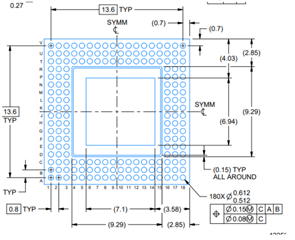
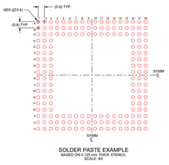
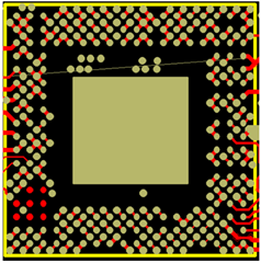
When the customer designed the iwar6843aop circuit, they found a difference in the ground pad between Datasheet and PCB design file, which made them curious.
* IWR6843AOP Drawing in Datasheet

* Solder Paste Example in Datasheet

* TI ' PCB design file.

They said the ground pad is found in the middle of the IC in the reference PCB design file, but can't see the ground part in the Datasheet Solder Paste Example, so please let me know why.
Since they would like to clarify about Ground pad while drawing PCB cad library. Please let us know how they should handle it.
Thanks.
Regards,
Jack


